

Artificial muscle device and driving method thereof
A technology of artificial muscles and permanent magnets, applied in the field of bionic robots, can solve problems such as increasing costs, and achieve the effects of facilitating replacement, avoiding losses, and improving force support.
- Summary
- Abstract
- Description
- Claims
- Application Information
AI Technical Summary
Problems solved by technology
Method used
Image

Examples
Embodiment Construction
[0026] The standard parts used in the present invention can be purchased from the market, and the special-shaped parts can be customized according to the instructions and the accompanying drawings. The specific connection methods of each part adopt mature bolts, rivets, welding in the prior art , pasting and other conventional means, no longer described in detail here.
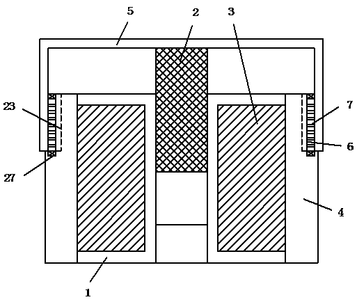
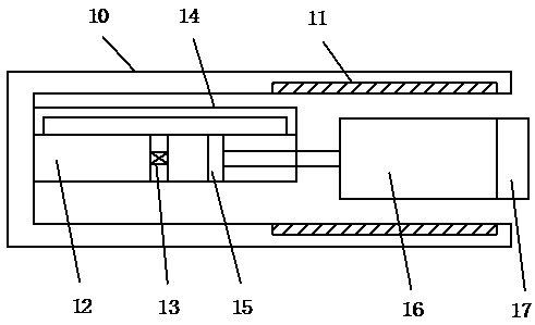
[0027] refer to Figure 1-7 A specific embodiment of the present invention includes a bobbin 1, a permanent magnet 2 is movably inserted into the inner side of the bobbin 1, a first electromagnetic coil 3 is wound on the outside of the bobbin 1, and a yoke 4 is arranged on the outside of the first electromagnetic coil 3, A stopper 5 is fixed on the first permanent magnet 2, and the stopper 5 is in sliding contact with the yoke 4; a chute 6 is arranged on the surface of the yoke 4, and several electromagnetic magnets are arranged on the contact surface between the stopper 5 and the yoke 4. The damper 7, the el...
PUM
 Abstract
Description
Claims
Application Information