Inclined strut type overrunning clutch

A technology of overrunning clutch and diagonal bracing, which is applied in clutches, one-way clutches, mechanical equipment, etc. to improve the stability of wedge tightening and torsion transmission, increase volume, and facilitate processing and manufacturing.

Active Publication Date: 2021-02-05
LUOYANG BEARING RES INST CO LTD
View PDF17 Cites 1 Cited by
  • Summary
  • Abstract
  • Description
  • Claims
  • Application Information

AI Technical Summary

Problems solved by technology

[0005] The purpose of the present invention is to provide a sprag type overrunning clutch to solve the problem in the prior art that the centrifugal engagement type clutch can be changed into a centrifugal disengagement type clutch by replacing the sprag or the centrifugal disengagement type clutch can be further reduced. Technical Problems of Frictional Resistance Between Wedges and Inner and Outer Raceways in Start-up Conditions

Method used


Image

  • Inclined strut type overrunning clutch
  • Inclined strut type overrunning clutch
  • Inclined strut type overrunning clutch

Examples


specific Embodiment 1

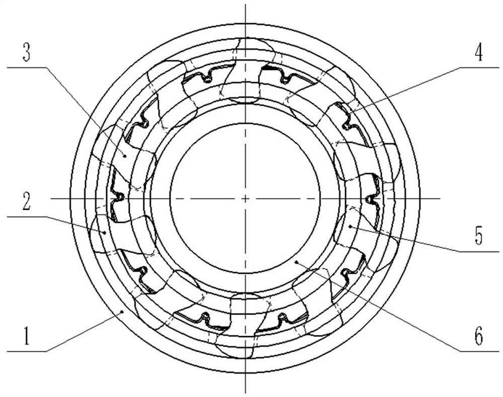
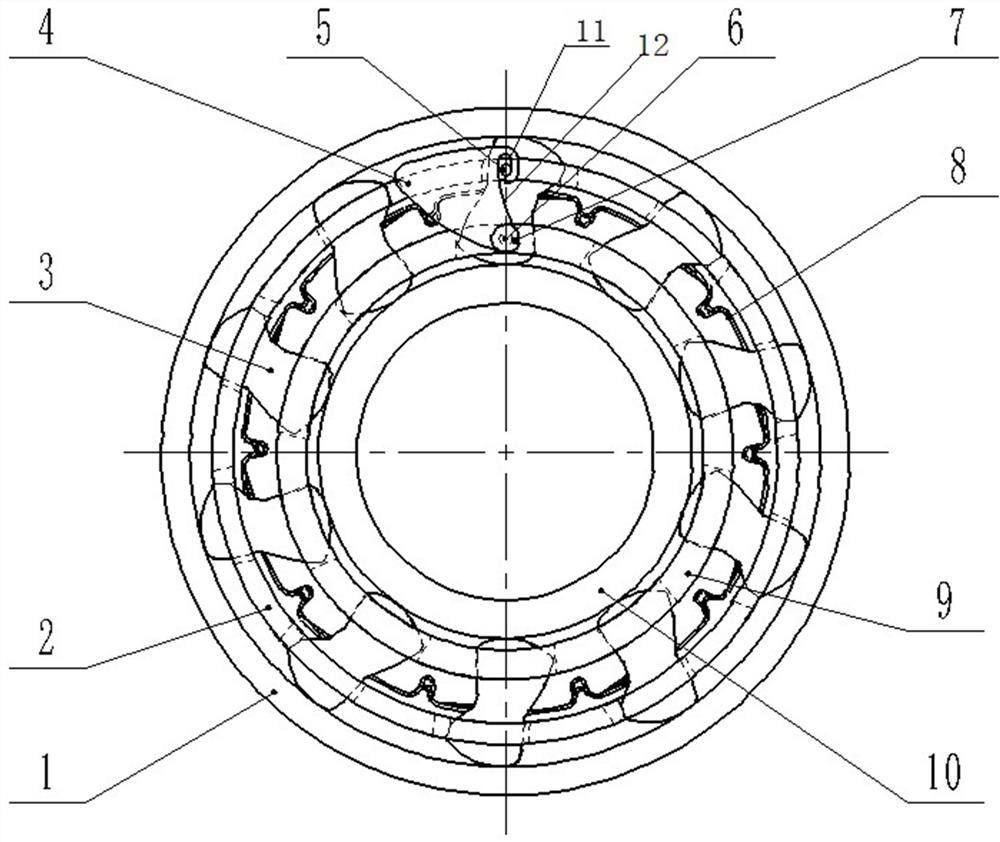
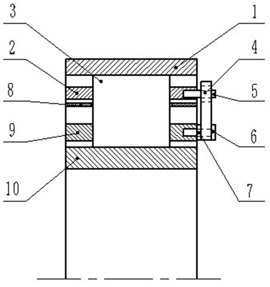
[0047] Such as Figure 2 to Figure 5 As shown, the sprag type overrunning clutch in this embodiment includes an inner ring 10, an inner cage 9, a wave spring 8, an outer cage 2, and an outer ring 1 arranged sequentially from inside to outside. The inner ring 10 and the outer ring 1 There are several wedges 3 arranged in between, and all the wedges 3 are distributed at intervals in sequence along the circumference of the inner ring 10, and all the wedges 3 are correspondingly distributed in the window holes of the inner cage 9, the wave spring 8 and the outer cage 2 Inside, and use the wave spring 8 to apply elastic force to each wedge 3, forcing the wedge 3 to maintain pressure contact with the inner raceway of the inner ring 10 and the outer raceway of the outer ring 1, so as to realize the normal operation beyond the cage.

[0048] In this embodiment, the inner ring 10 is used for transmission connection with the active part. In the state of torque transmission, the wedge bl...

specific Embodiment 2

[0058] The main difference between it and Embodiment 1 is that in Embodiment 1, the position of the center of gravity of the wedge makes the overrunning clutch a centrifugal disengagement type clutch, and the adjustment block can be used to further reduce the wear of the wedge working surface and the inner and outer raceways. In this embodiment, the center position of the wedge makes the overrunning clutch a centrifugal engagement type. In order to transform it into a centrifugal disengagement clutch, an adjustment block is arranged here. Under the action of centrifugal force, the adjustment block drives the inner and outer cages to rotate relative to each other. , forcing the wedge to swing in the direction of disengaging from the two raceways, which can effectively reduce the wear on the working surface of the wedge and the two raceways. The clutch can be successfully rebuilt without replacing the wedge. The structure is simple and easy to use.

specific Embodiment 3

[0060] The difference from Embodiment 1 mainly lies in that the adjustment block is hingedly connected with the inner cage through the hinge shaft, and is connected with the outer cage through the drive structure. In the overrunning state, the adjustment block swings under the centrifugal force. In this embodiment, the adjustment block is hingedly connected to the outer cage through the hinge shaft, and is connected to the outer cage through the drive structure. It is only necessary to ensure that the center of gravity of the adjustment block is located at the set side according to the actual working needs of the clutch. Here, The setting side refers to meeting the following requirements: when the sprag type overrunning clutch is in the overrunning condition, the adjustment block swings around the hinge shaft by the centrifugal force, and the two cages are driven to rotate relative to each other through the driving structure, and then all the wedges are driven to disengage synch...


PUM


Abstract

The invention relates to an inclined strut type overrunning clutch. The inclined strut type overrunning clutch comprises an inner ring, an inner retainer, a wave spring, an outer retainer, an outer ring and wedge blocks, and further comprises an adjusting block, the adjusting block is hinged to one retainer and is in transmission connection with the other retainer through a driving structure, andthe driving structure comprises a guide column and a guide rail part which are in guide moving fit; and the gravity center of the adjusting block is located on the corresponding side of the connectingline of a hinge shaft and the guide column, when the inclined strut type overrunning clutch is in an overrunning working condition, the adjusting block swings around the hinge shaft under centrifugalforce, the two retainers are driven by the driving structure to rotate in a relatively staggered mode, and then all the wedge blocks are driven to synchronously swing towards the direction separatedfrom an inner roller path and an outer roller path. The elastic acting force applied to the wedge blocks by the wave spring can be effectively counteracted, the actual pressure of the wedge blocks onthe inner roller path is reduced, the friction resistance is reduced, the abrasion of the acting surfaces of the wedge blocks can be effectively reduced, and the performance of the overrunning clutchis improved.

Description

technical field [0001] The invention belongs to the technical field of overrunning clutches, in particular to a sprag type overrunning clutch. Background technique [0002] The sprag-type overrunning clutch has a wide range of applications in the aviation field, such as the main transmission system of helicopters, the starting system of fixed-wing aircraft, and auxiliary power systems. [0003] Such as figure 1 As shown, the conventional sprag type overrunning clutch is composed of inner ring 6, outer ring 1, sprag 3, inner cage 5, outer cage 2 and wave spring 4, and the inner ring 6 and outer ring can be Torque is transmitted between 1, and the inner ring 6 and outer ring 1 are operated relatively independently under overrunning conditions, and the wedge 3, the inner cage 5, the outer cage 2 and the wave spring 4 follow the rotation of the outer ring 1, and the inner retainer The function of the frame 5 and the outer cage 2 is to keep the phases of the wedges 3 consistent...

Claims


Application Information

Patent Timeline
IPC IPC(8): F16D41/069
CPCF16D41/069F16D2041/0603F16D2041/0605F16D41/07
Inventor 宗晓明杨立光权思佳权超健徐润润马磊孟鸿超王永平
Owner LUOYANG BEARING RES INST CO LTD
Why Eureka
Try Eureka