

Subway rail damping device
A technology of shock absorbing device and track, which is applied in the direction of track, spring/shock absorber, road, etc., can solve the problems of poor shock absorption effect, achieve good shock absorption effect and slow down the effect of rebound force
- Summary
- Abstract
- Description
- Claims
- Application Information
AI Technical Summary
Problems solved by technology
Method used
Image

Examples
Embodiment 1
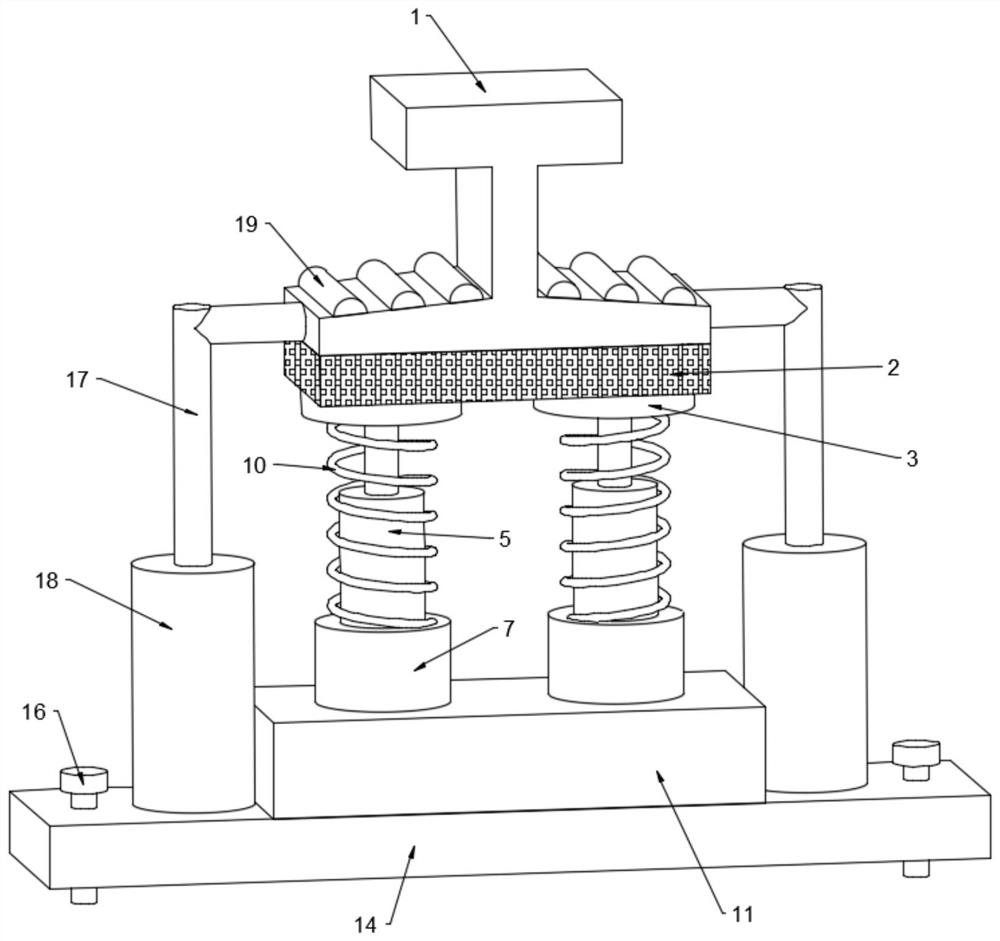
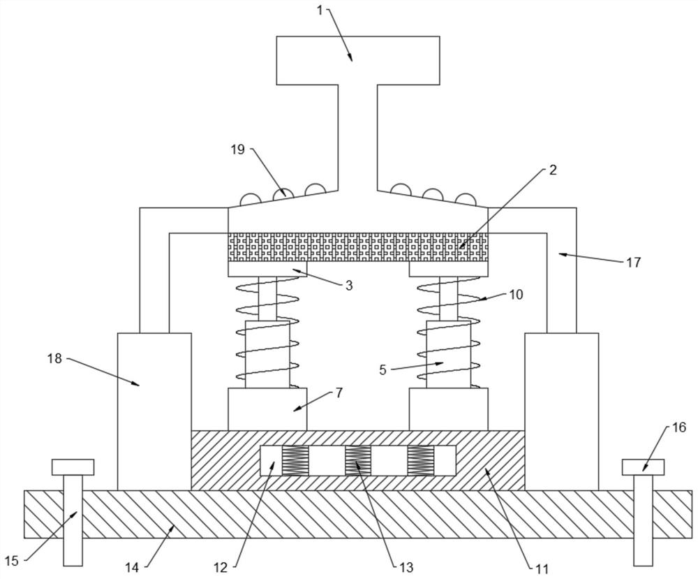
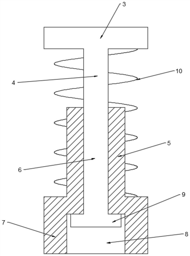
[0021] see Figure 1~3 , in an embodiment of the present invention, a subway track damping device includes a track 1, a bottom pad 2 is provided at the lower end of the track 1, the bottom pad 2 can play a role of shock absorption and buffering for the track 1, and the bottom pad 2 is provided with a There is a support plate 3, the lower end of the support plate 3 is fixedly connected with a support rod 4, the lower end of the support rod 4 is provided with a sleeve 5, the sleeve 5 is provided with a groove-6, and the support rod 4 is slidably installed in the groove-6 to support The rod 4 can slide up and down in the first groove 6, driving the support plate 3 to move up and down, the lower end of the sleeve 5 is integrally connected with the bottom cylinder 7, the bottom cylinder 7 is provided with a groove two 8, and the lower end of the support rod 3 is integrated Connected with the boss 9, the boss 9 is slidably installed in the groove two 8, the diameter of the boss 9 is...
Embodiment 2
[0027] In order to further increase the damping effect of the track 1, this embodiment is further improved on the basis of embodiment 1. The improvement is: the track 1 is provided with a damping pad 19, which can damp the subway , when the subway was running on the track 1, the damping pad 19 can play a good damping effect.
[0028] The working principle of this embodiment is: in order to further increase the damping effect of the track 1, a damping pad 19 is set on the track 1, and the damping pad 19 can damp the subway. When the subway is running on the track 1, Shock-absorbing pad 19 can play a good shock-absorbing effect.
[0029] To sum up, by setting the spring one 10, the spring one 10 can slow down the speed of the support plate 4 moving downward, and play a role in buffering the track 1. When encountering uneven road sections, the spring one 10 can also play a role in shock absorption The effect of ensuring the smooth operation of the subway; by setting the bottom c...
PUM
 Abstract
Description
Claims
Application Information