Linear actuator for kitchen and bath integrated cooker and integrated cooker turning plate
A technology of linear actuators and integrated stoves, applied in the field of integrated stoves, can solve the problems of user inconvenience, shrinkage of linear actuators, poor self-locking ability, etc.
- Summary
- Abstract
- Description
- Claims
- Application Information
AI Technical Summary
Problems solved by technology
Method used
Image

Examples
Embodiment 1
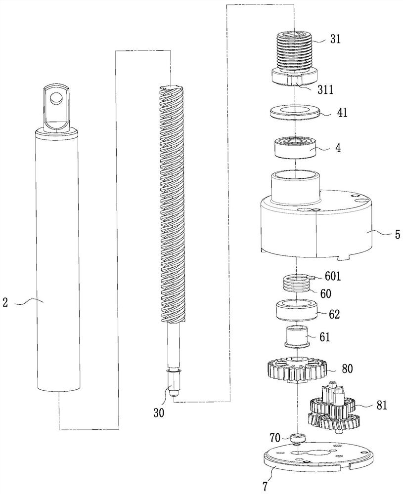
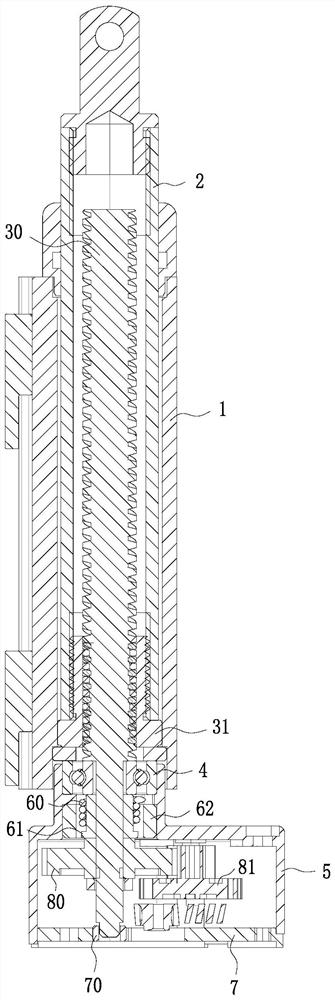
[0035] Such as Figure 1 to Figure 9 As shown, this embodiment shows a linear actuator for an integrated kitchen and bathroom, including an outer tube 1, an inner tube 2, a drive screw 30, a screw nut 31 and a drive for driving the drive screw 30 to rotate. The driver, the inner tube 2 is sleeved inside the outer tube 1, and the inner tube 2 can move axially along the outer tube 1, the transmission screw 30 is arranged inside the inner tube 2, and the transmission screw 30 is provided with a wire A rod nut 31, the screw nut 31 is fixedly connected with the inner tube 2, a gear box 5 is arranged between the driver and the transmission screw rod 30, and a gear box 5 is set on the transmission screw rod 30 to limit the linear actuation. The self-locking torsion spring 60 lowered by the device, the self-locking torsion spring 60 is fixed inside the gear box 5, the transmission screw 30 is sleeved with a bearing 4 for load bearing, and the inside of the gear box 5 is provided with ...
Embodiment 2
[0044] Such as Figure 10 As shown, the difference between this embodiment and Embodiment 1 is that the self-locking torsion spring 60 is above the carrying platform 50. When the self-locking torsion spring 60 is above the carrying platform 50, the self-locking torsion spring 60 is driving The self-locking direction of the screw mandrel 30 changes, and when the transmission screw mandrel 30 rotates forward, the torsion spring seat 61 generates a torsion force on the inner wall of the self-locking torsion spring 60, and the self-locking torsion spring 60 passes through the pin 601 and the notch 51 The fixation of the self-locking torsion spring 60 will generate a reverse torque, so that the self-locking torsion spring 60 will hold the torsion spring seat 61 tighter and tighter, so that the transmission screw 30 cannot rotate, and then the transmission screw 30 will be forward. Rotating self-locking, the self-locking torsion spring 60 will gradually loosen the torsion spring sea...
Embodiment 3
[0047] This embodiment shows an integrated cooker flap, which includes a linear actuator for controlling the movement of the flap, wherein the linear actuator is implemented as in Embodiment 1 or Embodiment 2 or other identical implementations. The linear actuator described in the example, this embodiment has a strong self-locking ability and stability, and can meet the needs of customers to a greater extent.
PUM
 Abstract
Description
Claims
Application Information
 - R&D
- Intellectual Property
- Life Sciences
- Materials
- Tech Scout
- Unparalleled Data Quality
- Higher Quality Content
- 60% Fewer Hallucinations
Browse by: Latest US Patents, China's latest patents, Technical Efficacy Thesaurus, Application Domain, Technology Topic, Popular Technical Reports.
© 2025 PatSnap. All rights reserved.Legal|Privacy policy|Modern Slavery Act Transparency Statement|Sitemap|About US| Contact US: help@patsnap.com