Adjustable LED lamp lighting device

A technology of LED lamps and lighting devices, applied in lighting devices, fixed lighting devices, lighting auxiliary devices, etc., can solve the problems of inability to adjust up and down, inconvenient for users to change, etc., and achieve the effect of safe and convenient use, scientific and reasonable structure

Inactive Publication Date: 2021-02-05
黄铁山
View PDF0 Cites 3 Cited by
  • Summary
  • Abstract
  • Description
  • Claims
  • Application Information

AI Technical Summary

Problems solved by technology

[0003] The purpose of the present invention is to provide an adjustable LED lamp lighting device to solve the problem that it cannot be adju

Method used


Image

  • Adjustable LED lamp lighting device
  • Adjustable LED lamp lighting device
  • Adjustable LED lamp lighting device

Examples


Embodiment 1

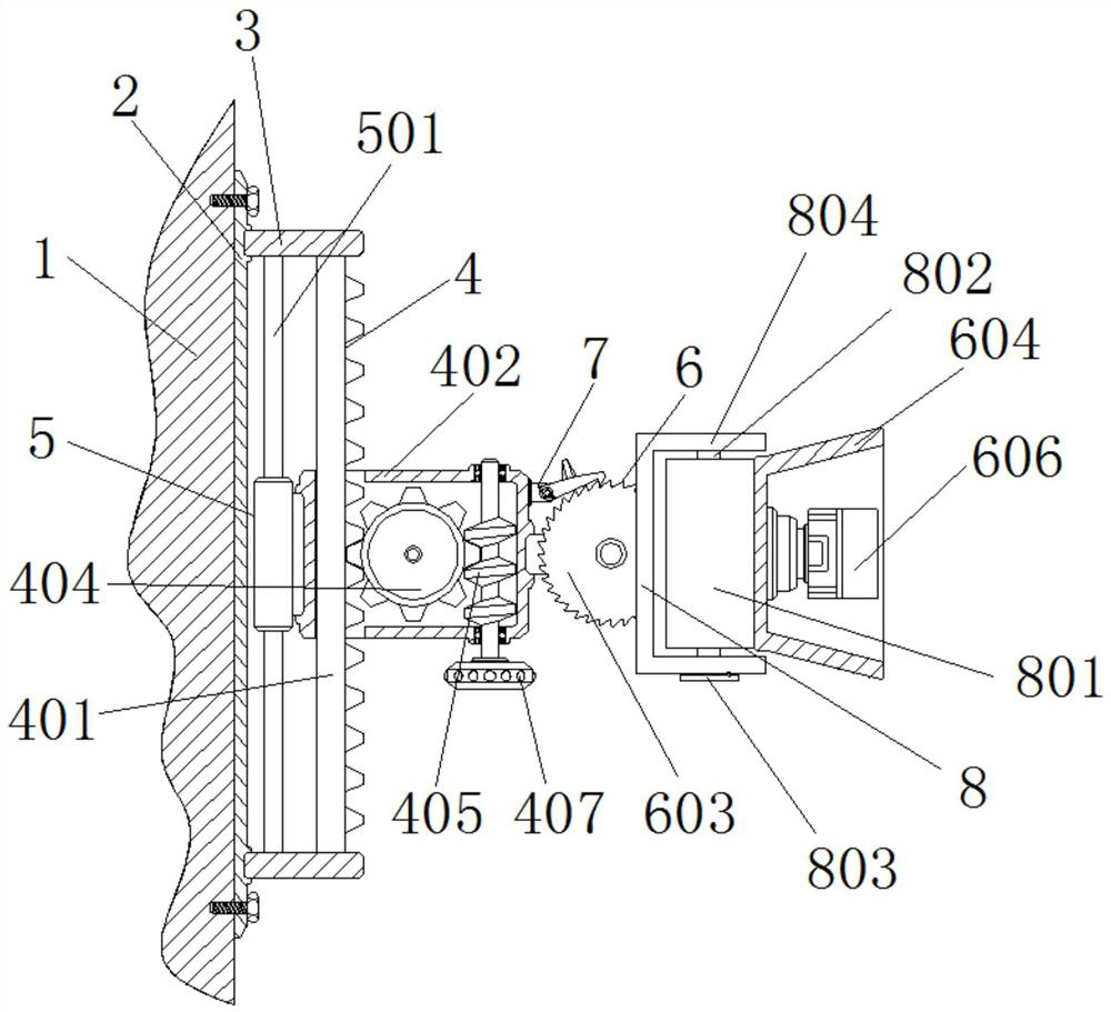
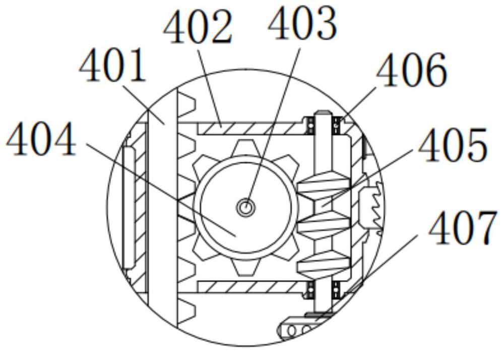
[0037] An adjustable LED lighting device, comprising a wall 1, a riser 2 is provided on the right side of the wall 1, a riser 2 is connected to the right side of the wall 1 through bolt threads, and the upper and lower right sides of the riser 2 are Both horizontal plates 3 are provided, the left side of the two horizontal plates 3 is fixedly connected with the right side of the vertical plate 2, and the inner side of the two horizontal plates 3 is provided with a lifting mechanism 4, and the lifting mechanism 4 includes a rack 401, a box body 402, the first connecting shaft 403, the worm gear 404, the worm 405, the bearing 406 and the handle 407, the rack 401 is arranged on the inner side of the two horizontal plates 3, and the top and bottom of the rack 401 are respectively fixed on the bottom of the top horizontal plate 3 And the top of the bottom horizontal plate 3, the outer wall gap of the rack 401 is matched with the box body 402, so that the box body 400 can carry out l...

Embodiment 2

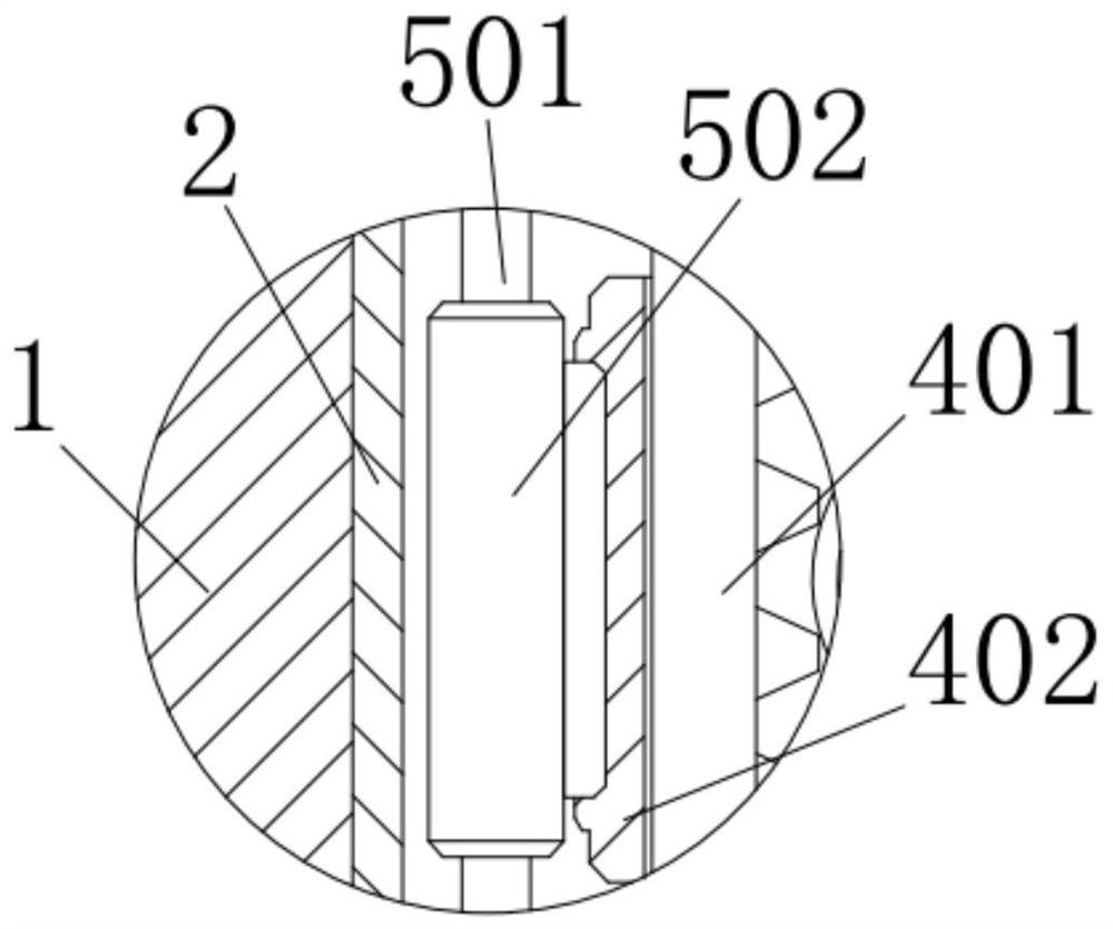
[0039] As an optional situation, in the new LED lamp lighting device, an auxiliary mechanism 5 is provided on the inner side of the two horizontal plates 3, and the auxiliary mechanism 5 includes a sliding rod 501 and a sliding sleeve 502, and the sliding rod 501 is arranged on the inner side of the two horizontal plates 3 , the top and bottom of the slide bar 501 are respectively fixed on the bottom of the top horizontal plate 3 and the top of the bottom horizontal plate 3, the outer wall of the slide bar 501 is provided with a sliding sleeve 502, and the inner wall of the sliding sleeve 502 is slidably connected with the outer wall of the slide bar 501 , the right side of the sliding sleeve 502 is fixedly connected with the left side of the box body 402, so that when the box body 402 moves up and down, the sliding sleeve 502 can be connected with the sliding rod 501 through sliding, and the outer wall of the rack 401 can be stabilized. For the lifting movement, the sliding ro...

Embodiment 3

[0042]As an optional situation, the new LED lamp lighting device, the right side of the box 402 is provided with an adjustment mechanism 6;

[0043] The adjustment mechanism 6 includes a cross bar 601, a ratchet 602, a second connecting shaft 603, a lampshade 604, a lamp holder 605 and an LED lamp 606;

[0044] The crossbar 601 is arranged on the right side of the box body 402, the left side of the crossbar 601 and the right side of the box body 402 are fixed together, the front end of the crossbar 601 is provided with a ratchet 602, and the crossbar 601 is provided with a ratchet 602. The front end surface of the rod 601 is provided with a second connecting shaft 603, and the ratchet 602 is rotationally connected with the front end surface of the cross bar 601 through the second connecting shaft 603. The right side of the ratchet 602 is provided with a C-shaped frame 804, and the C The two ends of the shaped frame 804 are rotatably connected with a rotating shaft 802, the rot...


PUM


Abstract

The invention discloses an adjustable LED lamp lighting device which comprises a wall body, a vertical plate is arranged on the right side of the wall body, a rack is arranged on the inner sides of two transverse plates, the top and the bottom of the rack are fixedly connected to the bottom of a top transverse plate and the top of a bottom transverse plate correspondingly, a box body is in clearance fit with the outer wall of the rack, and a worm wheel is arranged on the inner wall of the box body; the worm wheel is provided with a worm, the outer wall of the worm is meshed with the outer wallof the worm wheel, and the bottom of the worm wheel is fixedly connected with a handle. According to the novel LED lamp lighting device, the LED lamp can stably ascend and descend on the outer wall of the rack through rotation of the worm wheel and sliding connection of the sliding sleeve and the sliding rod, so that the LED lamp can rotate on the box body through the ratchet wheel, the ratchet wheel can drive the LED lamp to be subjected to angle adjustment, and the clamping rod can limit clockwise rotation of the ratchet wheel; and after the ratchet wheel drives the LED lamp to be subjectedto angle adjustment, the LED lamp can be stably placed.

Description

technical field [0001] The invention relates to the technical field of LED lamps, in particular to an adjustable LED lamp lighting device. Background technique [0002] The LED lamp is an electroluminescent semiconductor material chip, which is cured on the bracket with silver glue or white glue, and then connected to the chip and the circuit board with silver or gold wires, and sealed with epoxy resin around it to protect the inner core wire. The effect is to install the shell at last, so the LED lamp has good shock resistance. Although the existing LED lamp lighting device can realize lighting, it cannot be adjusted up and down according to the needs of users, and it is not convenient for users to change according to the needs of lighting. problem, and there is the problem that the existing LED lighting device cannot adjust the angle according to the needs of users. Contents of the invention [0003] The purpose of the present invention is to provide an adjustable LED l...

Claims


Application Information

Patent Timeline
IPC IPC(8): F21S8/00F21V21/30F21V21/34F21V21/36F21Y115/10
CPCF21S8/00F21V21/30F21V21/34F21V21/36F21Y2115/10
Inventor 黄铁山
Owner 黄铁山
Why Eureka
Try Eureka