Detection method for loss of riveting pin collar of truck brake beam pillar based on image inpainting

A technology of missing detection and braking beam, which is applied in the field of image recognition, can solve the problems of the missing detection method, poor accuracy, and low detection efficiency of the riveting pin collar of the braking beam pillar

Active Publication Date: 2021-05-11
HARBIN KEJIA GENERAL MECHANICAL & ELECTRICAL CO LTD
View PDF5 Cites 0 Cited by
  • Summary
  • Abstract
  • Description
  • Claims
  • Application Information

AI Technical Summary

Problems solved by technology

[0004] The purpose of the present invention is to solve the problem of low detection efficiency and poor accuracy when manually checking the loss of the brake beam pillar riveting pin collar in the prior art, and propose a truck brake beam pillar riveting pin bushing based on image restoration Ring loss detection method

Method used


Image

  • Detection method for loss of riveting pin collar of truck brake beam pillar based on image inpainting
  • Detection method for loss of riveting pin collar of truck brake beam pillar based on image inpainting
  • Detection method for loss of riveting pin collar of truck brake beam pillar based on image inpainting

Examples


specific Embodiment approach 1

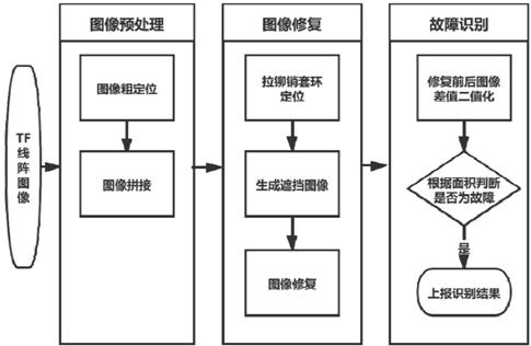
[0055] Specific implementation mode one: refer to figure 1 This embodiment will be specifically described. The method for detecting the loss of the riveting pin collar of the truck brake beam pillar based on image restoration in this embodiment includes the following steps:

[0056] Step 1: Obtain the linear image of the railway wagon;

[0057] Step 2: Carry out rough positioning of the brake beam pillar position according to the obtained linear image of the railway freight car;

[0058] Step 3: Binarize the image after rough positioning, and locate the position and direction of the brake beam pillar according to the area of ​​the black area in the binarized image. The specific steps are:

[0059] Step 31: Traverse the black areas in turn, and select the two areas with the largest areas as the edges of the brake beam pillars;

[0060] Step 3 and 2: Project the selected edge, and the position of the raised image obtained is the position of the angle iron of the brake beam pil...

specific Embodiment approach 2

[0075] Embodiment 2: This embodiment is a further description of Embodiment 1. The difference between this embodiment and Embodiment 1 is that the rough positioning of the brake beam strut in step 2 is based on the wheelbase information and the prior information of the brake beam strut. Check the location information.

[0076] Image Coarse Positioning

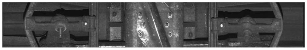
[0077] Using prior knowledge such as wheelbase information and component locations, the brake beam strut components can be roughly located, and then the brake beam strut area to be identified can be cut out from the large image of the whole train (such as figure 2 shown).

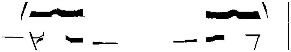
[0078] The image is reduced and then binarized (such as image 3 Shown), and filter according to the area of ​​the black connected area, the position and direction of the pillar can be located.

specific Embodiment approach 3

[0079] Embodiment 3: This embodiment is a further description of Embodiment 2. The difference between this Embodiment and Embodiment 2 is that the specific steps of Step 7 are:

[0080] Step 71: Calculate the affine correction parameters between the two brake beam pillars;

[0081] Step 72: Obtain the candidate position of the occlusion image according to the position of the occlusion mask in the occlusion image and the affine correction parameter, and then perform geometric transformation according to the candidate position of the occlusion image;

[0082] Step 73: Expand the candidate positions of the occluded image after geometric transformation up, down, left, and right to obtain the expanded image area, wherein the expanded image area is larger than the occluded image, and finally obtain the repaired image according to the expanded image area.

[0083] image restoration

[0084] ① Positioning of the riveting pin collar

[0085] According to the shadow area near the brak...


PUM


Abstract

A method for detecting the loss of the collar of the riveting pin of the brake beam pillar of the truck based on image restoration, which involves the field of image recognition technology, and aims at the low detection efficiency and accuracy of manual inspection of the loss of the collar of the riveting pin of the brake beam pillar in the prior art. In order to solve the problem of poor performance, automatic image recognition is used instead of manual detection to improve detection efficiency and accuracy. Different from the previous fault detection methods such as template matching and feature extraction, it uses the idea of ​​image repair to detect faults. When repairing the image, the left-right symmetry of the brake beam pillar and the uniform gray level distribution on the rivet pin collar are fully considered. At the same time, the neighborhood information and similar structural information of the image are used to improve the repair effect. Horizontally flip the images of the left and right pillars on the same brake beam and stitch them together, use the extracted vanishing point estimation to perform GMS matching, calculate the affine correction parameters, and use them as constraints for image restoration, greatly improving the speed of image restoration .

Description

technical field [0001] The invention relates to the technical field of image recognition, in particular to a method for detecting loss of a riveting pin collar of a truck brake beam pillar based on image restoration. Background technique [0002] The loss of the riveting pin collar of the brake beam pillar is a failure that endangers driving safety. The traditional brake beam station uses automatic image collection and manual image inspection for fault detection. With the increasing traffic volume of railway freight cars, in order to ensure train inspection time, a large number of inspectors are required, and the labor intensity is extremely high. In addition, vehicle inspectors need to face a large number of images every day, which is prone to fatigue, missed inspections, false inspections, and endangering driving safety. [0003] Unlike deep learning, which requires expensive GPU equipment investment, the image processing method can be used to realize the automatic identi...

Claims


Application Information

Patent Timeline
Patent Type & Authority Patents(China)
IPC IPC(8): G06K9/34G06T7/62B60T17/22
CPCG06T7/62B60T17/22G06V10/267
Inventor 高恩颖
Owner HARBIN KEJIA GENERAL MECHANICAL & ELECTRICAL CO LTD
Why Eureka
Try Eureka