
A wedge wire clamp

A technology of wedge-shaped wire clips and wedge-shaped blocks, which is applied in the direction of clamping/spring connection, electrical components, connections, etc., can solve the problems of reduced service life, poor contact of wires, easy loosening of bolts, etc., so as to improve service life and avoid poor contact , to avoid the effect of excessive heat

Active Publication Date: 2022-05-17
STATE GRID ZHEJIANG CIXI POWER SUPPLY +1
View PDF13 Cites 0 Cited by
  • Summary
  • Abstract
  • Description
  • Claims
  • Application Information

AI Technical Summary

Problems solved by technology

[0005] The purpose of the present invention is to provide a wedge-shaped clamp to solve the problems in the prior art that the bolts are easy to loosen, resulting in poor contact of the wires, and the closed loop is easy to cause overheating of the wires and reduce the service life.

Method used


Image

  • A wedge wire clamp
  • A wedge wire clamp
  • A wedge wire clamp

Examples


Embodiment Construction

[0029] The following will clearly and completely describe the technical solutions in the embodiments of the present invention with reference to the accompanying drawings in the embodiments of the present invention. Obviously, the described embodiments are only some, not all, embodiments of the present invention. Based on the embodiments of the present invention, all other embodiments obtained by persons of ordinary skill in the art without making creative efforts belong to the protection scope of the present invention.

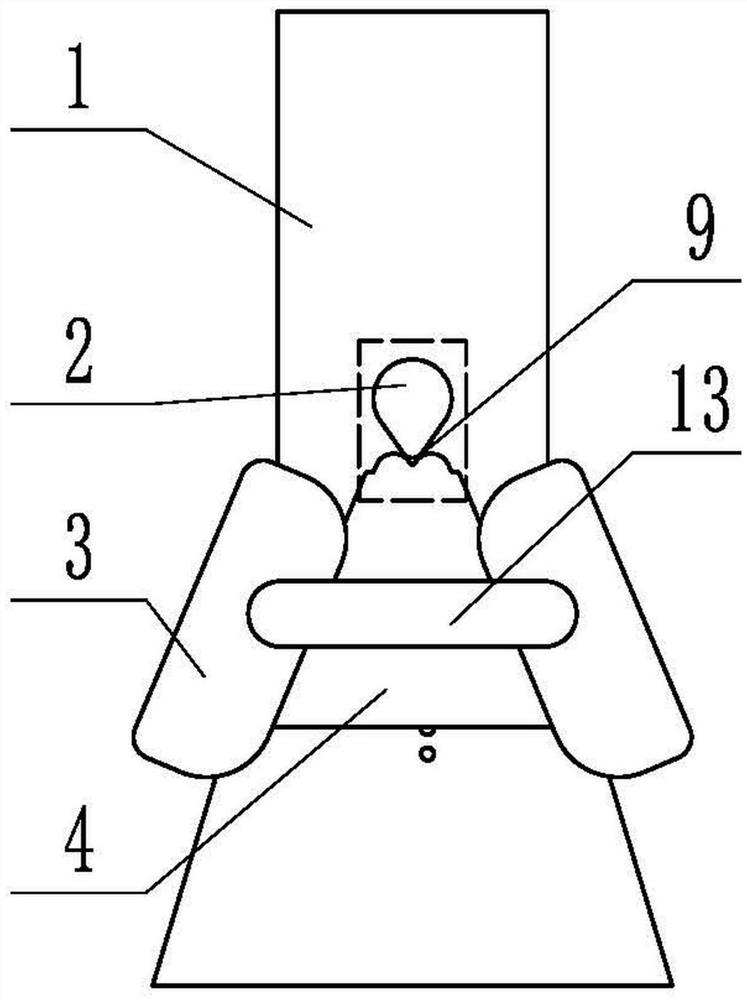
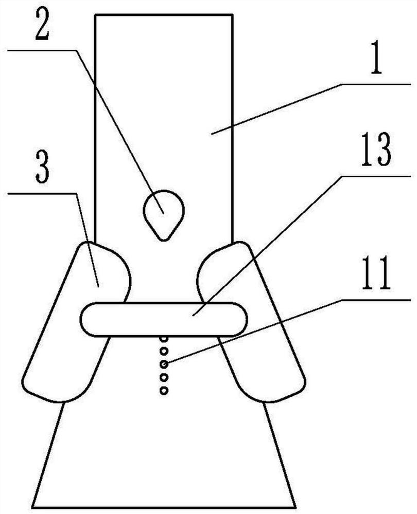
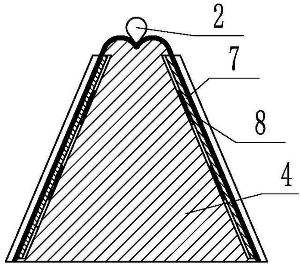
[0030] attached by Figure 1-6 It can be seen that the present invention provides a wedge-shaped wire clamp, which includes a body 1, on which a crimping column 2 is fixed, on which body 1 is provided with fixed blocks 3 placed on both sides of the crimping column 2, and crimping The column 2 is designed on the center line of the two fixed blocks 3, which can maintain a good centering effect, and also includes a wedge-shaped block 4 arranged between the two fi...


PUM


Abstract

A wedge-shaped wire clip, through the design of two fixed blocks and wedge-shaped blocks that are used in conjunction with each other, when in use, through the slopes with the same inclination on the fixed block and the wedge-shaped block, the wires are separated from the two sides of the wedge-shaped block and the corresponding sides respectively. The fixed block is clamped together, and the two strands of wires pass through the two sides of the wedge block and finally meet at the top of the wedge block for connection, and a non-closed connection is formed by designing the crimping post and the groove on the wedge block The two strands of wires are compressed by the grooves on the crimping post and the wedge-shaped block at the connection position. The invention can well realize the fixing of the wires and the non-closed compression effect on the connection position, and can effectively improve the safety of the wires. The service life and the contact effect of the wire connection part.

Description

technical field [0001] The invention relates to the technical field of electric power auxiliary devices, in particular to a wedge-shaped clamp. Background technique [0002] The splicing clamp is a contact fitting used to connect wires to transmit electrical loads. It has a wide range of applications and can be used for jumper splicing of non-linear poles and towers, connection of T wiring and branch lines at non-load-bearing connections of power systems, switches, transformers, etc. Electrical equipment down-lead connection, grounding down-lead connection, etc. [0003] At present, the splicing clamp usually clamps the wires in the clamping groove by bolts. Although the structure of the splicing clamp is simple, the phenomenon of bolt loosening often occurs during long-term operation, making the clamping of the splicing clamp The effect is reduced, which leads to poor contact of the wire and affects the normal operation of the wire. In order to prevent the bolts from loos...

Claims


Application Information

Patent Timeline
Patent Type & Authority Patents(China)
IPC IPC(8): H01R4/50H01R4/48
CPCH01R4/5083H01R4/4809Y02E10/50
Inventor 罗立华沈科炬戚正航骆祥明吴航飞杨跃平应雪莲邹翔
Owner STATE GRID ZHEJIANG CIXI POWER SUPPLY
Learn More