Handle-replaceable multifunctional garden trimming tool
A dressing tool, multi-functional technology, applied in gardening tools/equipment, cutting tools, gardening, etc., can solve the problems of high cost, poor quality of use by consumers with a single handle, and single use range, etc., to avoid accidental injury, design Ingenious, sturdy plug effect
- Summary
- Abstract
- Description
- Claims
- Application Information
AI Technical Summary
Problems solved by technology
Method used
Image
Examples
Embodiment 1
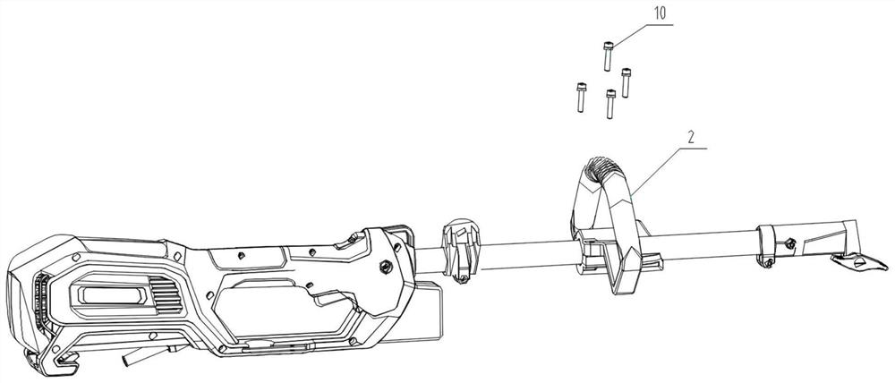
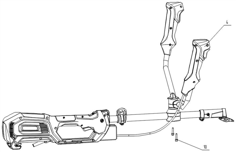
[0040]SeeFigure 1-14 , Including the rear handle 1, the connecting tube assembly 17, the auxiliary handle 2, the front handle assembly 4 and the tool head 3. The rear handle 1 is equipped with a motor assembly 11, and the output shaft end of the motor assembly 11 is connected with a transmission shaft through a transmission sleeve 12 One 14, and the transmission shaft 14 penetrates the connecting tube assembly 17 fixed in the rear handle 1, the connecting tube assembly 17 is sleeved with a strap buckle 18, and the end of the connecting tube assembly 17 has a connecting tube joint 26, a connecting tube joint 26 is a cylindrical cylinder and two ends of the cylinder are provided with expansion joints. The connecting pipe joint 26 has an embracing clamp and the clamp has a clamping knob 27. The connecting pipe joint 26 has an elastic device pull pin 28, and the connecting pipe The joint 26 is inserted and fixed with a tool head 3, and the connecting pipe joint 26 is used to replace the...
Embodiment 2
[0042]SeeFigure 1-14 , Between the connecting pipe joint 26 and the strap buckle 18, there are an auxiliary handle 2 and a front handle assembly 4 fixed on the connecting tube assembly 17. The auxiliary handle 2 and the front handle assembly 4 are used interchangeably. According to actual operation needs, the front handle assembly 4 The horn shape includes a left handle 29, a right handle 34 and a handle connecting tube 30 in the middle. The left handle 29 and the right handle 34 are screwed to both ends of the handle connecting tube 30. The handle connecting tube 30 is hinged with a connecting pin 33. The upper pressing plate 32 and the lower pressing plate 38, the upper pressing plate 32 and the lower pressing plate 38 are provided with mounting grooves for the handle connecting pipe 30, the lower end surface of the lower pressing plate 38 has a ring-shaped toothed boss, and the lower end of the lower pressing plate 38 has a fixed On the fixing seat upper 41 and the fixing seat lo...
Embodiment 3
[0044]SeeFigure 1-15The rear handle 1 is provided with a switch trigger 20 and a switch K121. The switch K121 is connected in series with a normally closed switch K223 and the switch K121 and normally closed switch K223 are connected in parallel with a socket 22. The switch trigger 20 is movably connected in the rear handle 1 and the switch The upper end surface of the trigger one 20 has an elastic component 19 fixed in the rear handle 1. The elastic component 19 is composed of a spring and a cylindrical member that fixes the spring. The rear handle 1 is equipped with a horizontally arranged anti-self-locking push button 15, reverse The side wall of the self-locking push button 15 abuts against the elastic member 16, and the bottom end of the anti-self-locking push button 15 abuts against the switch trigger 20. The rear handle 1 has a notch corresponding to the socket 22 and is located The inside of the rear handle 1 is provided with a push plate 24 on the notch, the side wall of th...
PUM
 Abstract
Description
Claims
Application Information
 - R&D
- Intellectual Property
- Life Sciences
- Materials
- Tech Scout
- Unparalleled Data Quality
- Higher Quality Content
- 60% Fewer Hallucinations
Browse by: Latest US Patents, China's latest patents, Technical Efficacy Thesaurus, Application Domain, Technology Topic, Popular Technical Reports.
© 2025 PatSnap. All rights reserved.Legal|Privacy policy|Modern Slavery Act Transparency Statement|Sitemap|About US| Contact US: help@patsnap.com


