Self-cleaning device and cleaning method in waste gas treatment process

A technology for waste gas treatment and self-cleaning, applied in separation methods, chemical instruments and methods, transportation and packaging, etc., can solve problems such as inability to clean the filter screen, inability to effectively filter waste gas, and blockage.

Inactive Publication Date: 2021-02-09
江苏旭龙环境科技有限公司
View PDF6 Cites 0 Cited by
  • Summary
  • Abstract
  • Description
  • Claims
  • Application Information

AI Technical Summary

Problems solved by technology

[0004] The purpose of the present invention is to provide a self-cleaning device in the process of waste gas treatment, which is used to solve the problem that in the prior art, when the filter screen is used for a long time during the treatment of waste gas, it will cause blockage and cannot effectively filter the impurities in the waste gas, and cannot continue to transport the waste gas The problem of cleaning the filter screen at the same time

Method used


Image

  • Self-cleaning device and cleaning method in waste gas treatment process
  • Self-cleaning device and cleaning method in waste gas treatment process
  • Self-cleaning device and cleaning method in waste gas treatment process

Examples


Embodiment 1

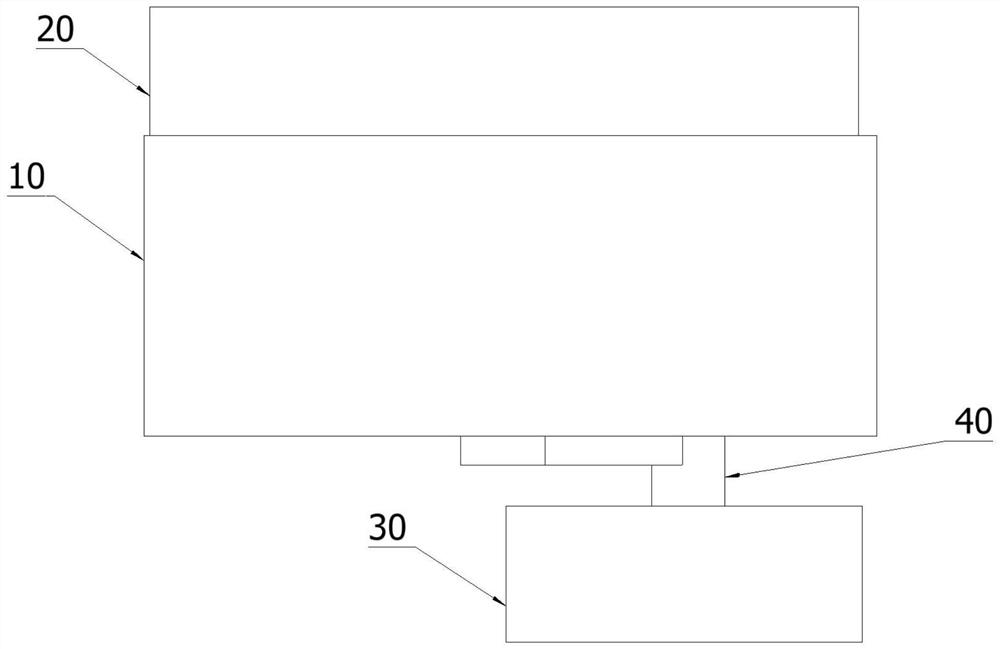
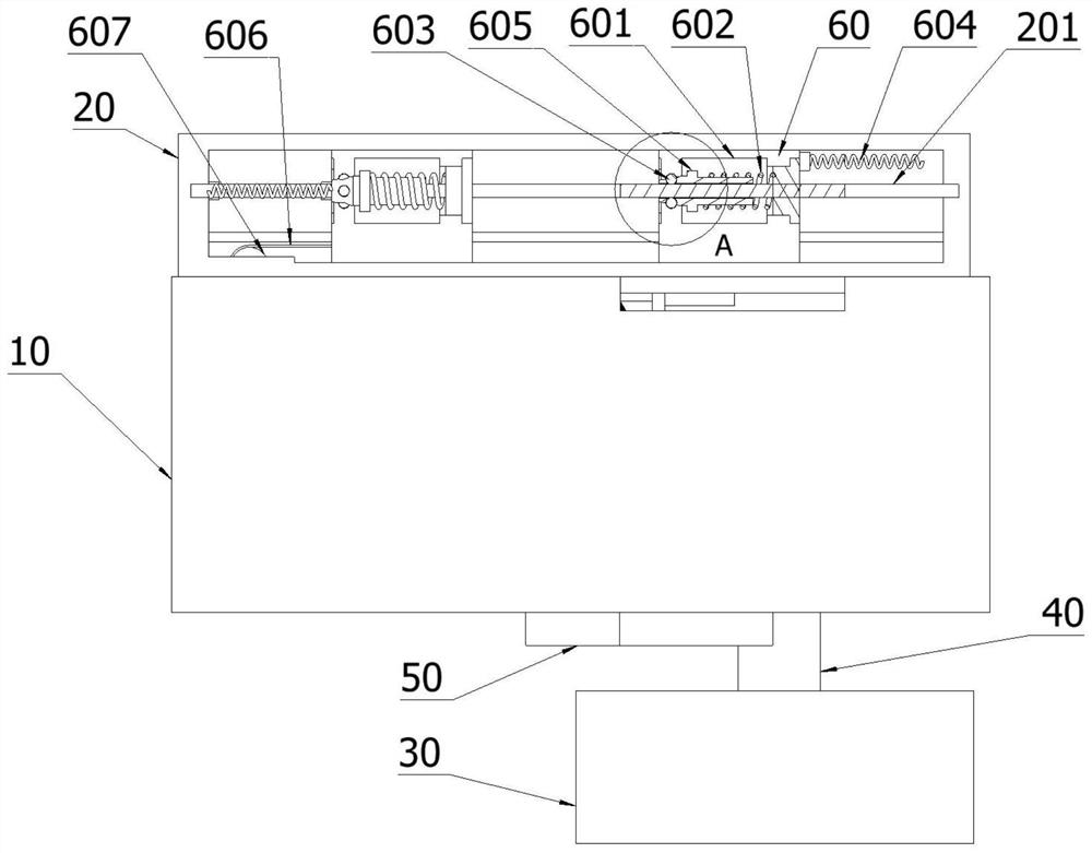
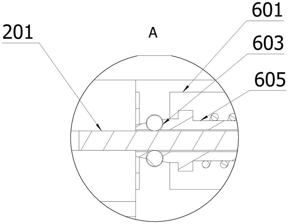
[0050] Such as figure 1 , 2 , 4, this embodiment discloses a self-cleaning device in the waste gas treatment process, including: an outer channel 10, an inner channel 101, an auxiliary ventilation plate 102, an air outlet channel 103, a housing 20, a driving device 60, a cleaning Device 70, closing device 90, the inside of the outer passage 10 is hollow; the inner passage 101 is arranged inside the outer passage 10, the inner passage 101 is connected with the outer passage 10, and the inside of the inner passage 101 is hollow; the auxiliary ventilation plate 102 is arranged in the inner passage The lower surface of 101, the auxiliary ventilation plate 102 is connected with the inner channel 101; the air outlet channel 103 is arranged on the right side of the auxiliary ventilation plate 102, and there is a distance between the air outlet channel 103 and the auxiliary ventilation plate 102, and the inside of the air outlet channel 103 It is hollow, and a filter screen 80 is arr...

Embodiment 2

[0061] Same as Embodiment 1, as shown in Figures 6 and 7, one end of the control rod 903 is also connected to the cover plate 105. The circular hole is matched, the cover plate 105 is connected with the driving device 60 in the right position, the adjustment frame 104 is connected with the driving device 60 in the left position, and the adjustment frame 104 approaches the filter screen 80 when driven by the left driving device 60 The cleaning device 70 cleans near the surface of the filter screen 80 , and drives the right side driving device 60 to move through the connecting belt 606 when the left driving device 60 moves and closes the cover plate 105 to the circular hole of the air outlet channel 103 . When the cover plate 105 moves through the control rod 903, the control rod 903 drives the connecting plate 902 to move to the right through the gear, so that the originally closed closing plate 901 is opened, and the exhaust gas can pass through the auxiliary ventilation plate ...

Embodiment 3

[0063] Such as Figure 8 , 9 As shown, the embodiment of the present invention also discloses a cleaning method for a self-cleaning device in the waste gas treatment process, including the following steps:

[0064] The external air supply pipe is connected with the external channel 10, and the waste gas is passed into the external channel 10 through the air supply pipe. After entering the external channel 10, the exhaust gas passes through the auxiliary ventilation plate 102 and the air outlet channel 103 to divide the exhaust gas into two streams;

[0065] The exhaust gas entering the auxiliary ventilation plate 102 continues to move to the right through the filter screen 80 to filter the exhaust gas impurities, and the filtered exhaust gas flows to the air outlet channel 103. Since the sealing device 90 inside the air outlet channel 103 is still in a closed state at this time, the filtered exhaust gas Do not enter the air outlet channel 103 and diverge to the periphery of t...


PUM


Abstract

The invention discloses a self-cleaning device in a waste gas treatment process, and relates to the technical field of gas environmental protection. According to the self-cleaning device in the wastegas treatment process, the interior of an outer channel is hollow; an inner channel is arranged in the outer channel; an auxiliary ventilation plate is arranged on the lower surface of the inner channel; an air outflow channel is arranged on the right side of the auxiliary ventilation plate, and a filter screen is arranged on the left side of the air outflow channel; a placing shell is arranged onthe upper surface of the outer channel, and a sliding rod is fixedly connected with the placing shell; a driving device is arranged in the placing shell; a cleaning device is arranged between the auxiliary ventilation plate and the air outflow channel; and a sealing device is arranged in the air outflow channel. In the prior art, when waste gas is treated, a filter screen is blocked after being used for a long time, impurities in the waste gas cannot be effectively filtered out, and the filter screen cannot be cleaned while the waste gas is continuously conveyed. With the self-cleaning deviceand cleaning method in the waste gas treatment process of the invention adopted, the above problem can be solved.

Description

technical field [0001] The invention relates to the technical field of gas environmental protection, in particular to a self-cleaning device and a cleaning method in the waste gas treatment process. Background technique [0002] When treating exhaust gas, in order to meet environmental protection requirements, the exhaust gas is generally firstly filtered and then filtered to filter out large and small particles in the exhaust gas, followed by activated carbon to absorb the odor, and then the treated gas into the external environment. [0003] At present, the exhaust gas treatment equipment commonly used for easy cleaning of the exhaust gas outlet is not convenient for cleaning the impurities at the air outlet. After the filter is used for a long time, a large amount of impurities will remain in the filter and cause the filter to be blocked, which will increase the internal pressure of the pipeline. If not Replacing and cleaning the filter screen in time will cause serious ...

Claims


Application Information

Patent Timeline
IPC IPC(8): B01D46/10B01D46/00
CPCB01D46/10B01D46/0002B01D46/681
Inventor 曹静芳
Owner 江苏旭龙环境科技有限公司
Why Eureka
Try Eureka