Sewage pretreatment equipment for sewage treatment plant

A sewage pretreatment and sewage treatment plant technology, applied in the direction of filtration separation, separation method, mobile filter element filter, etc., can solve the problems of poor applicability, insufficient energy saving and environmental protection, etc.

Inactive Publication Date: 2020-10-23
宋卫校
View PDF10 Cites 3 Cited by
  • Summary
  • Abstract
  • Description
  • Claims
  • Application Information

AI Technical Summary

Problems solved by technology

[0004] The purpose of the present invention is to solve the shortcomings of traditional sewage pretreatment equipment in the prior art, such as poor applicability, or insufficient energy saving and environmental protection, and propose a sewage pretreatment equipment for sewage treatment plants

Method used


Image

  • Sewage pretreatment equipment for sewage treatment plant
  • Sewage pretreatment equipment for sewage treatment plant
  • Sewage pretreatment equipment for sewage treatment plant

Examples


Embodiment 1

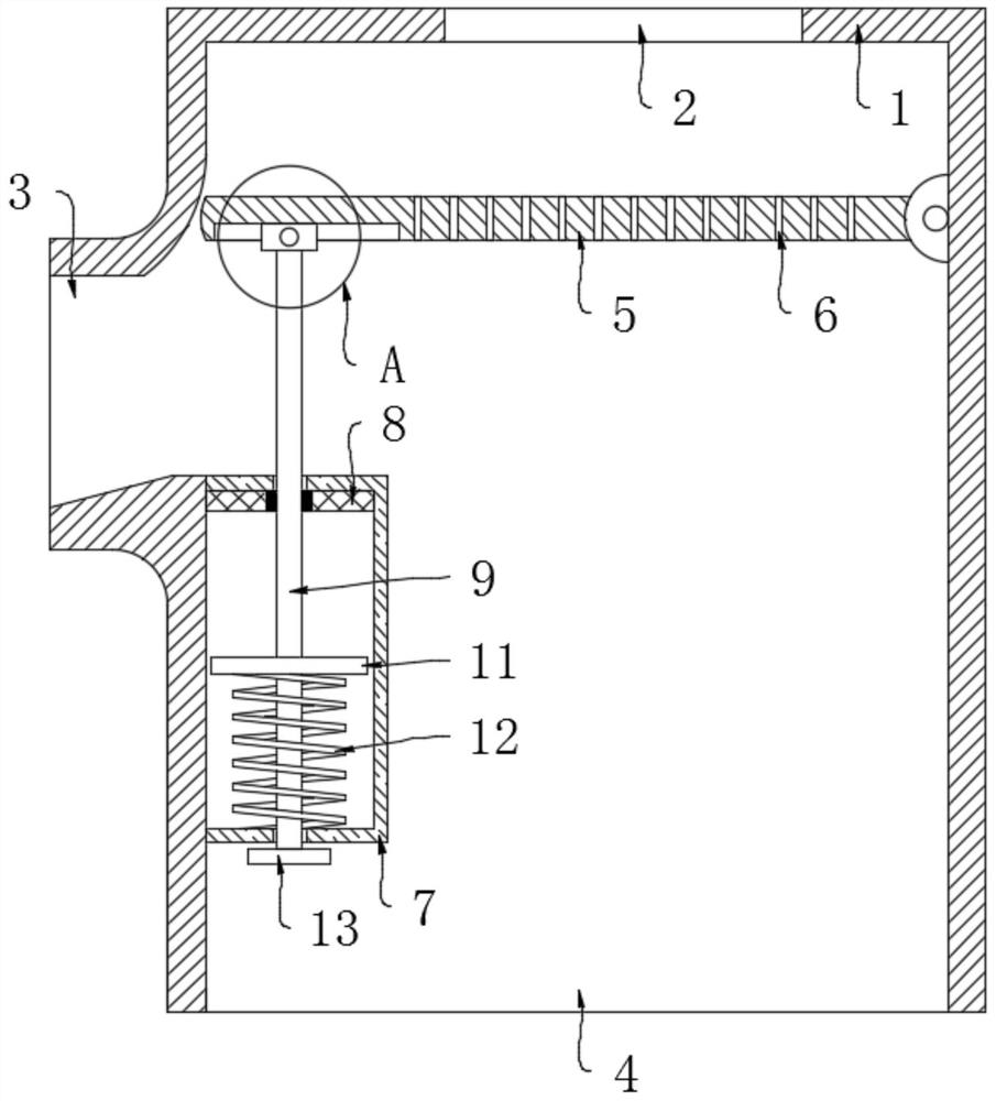
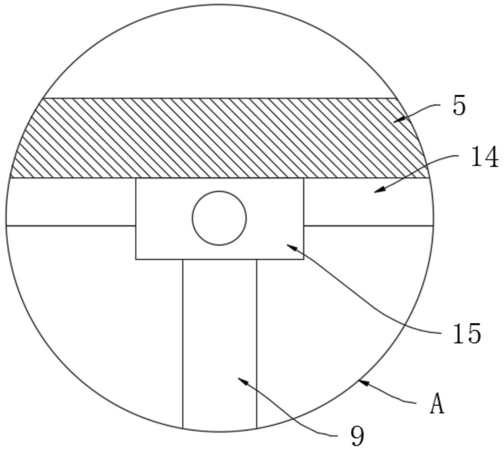
[0020] refer to Figure 1-3 , a kind of sewage pretreatment equipment for sewage treatment plants, comprising a box body 1, a water inlet 2 is opened on the upper end surface of the box body 1, a slag discharge port 3 is opened on the side wall of the box body 1, and a drain outlet 4 is opened on the lower end surface of the box body 1 , the inner wall of the box body 1 away from the slag discharge port 3 is connected to the rotary plate 5 through the rotation of the pin shaft, and the end of the rotary plate 5 close to the slag discharge port 3 and the top of the slag discharge port 3 are chamfered, and the rotary plate A plurality of water permeable holes 6 opposite to the water inlet 2 are evenly opened on the 5, and the plurality of water permeable holes 6 and the water inlet 2 are located on the side close to the pin shaft, and the water falling from the water inlet 2 to the rotating plate 5 falls on the The rotating plate 5 is close to the side of the pin shaft to form a...

Embodiment 2

[0024] Compared with the prior art, the difference between this embodiment and the embodiment is that: slide rails 16 are symmetrically arranged on the rotating plate 5, and each slide rail 16 is elastically connected with a counterweight 18 through a return spring 17, and each Each counterweight 18 is slidably connected with the slide rail 16, and the return spring 17 is positioned at the side close to the pin shaft. A scraper 19 is fixedly connected between the plurality of counterweights 18, and the lower end of the scraper 19 is connected to the rotating plate 5. sliding connection on the upper surface.

[0025] In this embodiment, when there are too many sundries on the upper end surface of the rotating plate 5 and the counterweight 18 slides to the low point in the corresponding slide rail 16 under its own gravity and stretches the return spring 17, then the two counterweights 18 Jointly drive the scraper 19 to clean up the debris on the upper end surface of the rotary p...


PUM


Abstract

The invention discloses sewage pretreatment equipment for a sewage treatment plant. The equipment comprises a tank body, wherein a water inlet is formed in the upper end surface of the tank body; a slag discharging opening is formed in the side wall of the tank body; a water outlet is formed in the lower end surface of the tank body; a rotating plate is rotationally connected to the inner wall ofthe side, away from the slag discharging opening, of the tank body through a pin shaft; a plurality of water permeable holes opposite to the water inlet are evenly formed in the rotating plate; a plurality of control mechanisms are symmetrically arranged between the rotating plate and the inner wall of the tank body; and each control mechanism comprises a mounting box fixedly connected to the inner wall of the side, close to the slag discharging opening, of the tank body. The first permanent magnet disc and the second permanent magnet disc are arranged; sewage can be continuously filtered by utilizing potential energy of sundries on the upper end face of the rotating plate, the sundries on the upper end face of the rotating plate are discharged into the slag discharging opening, input of manpower and external electric power energy sources is not needed, input of manpower resources is reduced, energy conservation and environmental protection are achieved, continuous work can be achieved, and the using effect is good.

Description

technical field [0001] The invention relates to the technical field of sewage treatment, in particular to sewage pretreatment equipment for sewage treatment plants. Background technique [0002] Due to the complex composition of urban sewage, general sewage treatment plants need to pretreat these sewage before treating them. The grille is generally used as the first process in the pretreatment, which is mainly used to intercept and filter some larger sewage. of sundries. [0003] In actual use, the grille intercepts the sundries and removes them by manual salvage. However, the daily sewage treatment volume of the sewage treatment plant fluctuates greatly. When it is blocked, it will have a great impact on the subsequent treatment process. Although there are some existing mechanical salvage equipment, the continuous operation of these mechanical equipment often consumes a lot of energy, which does not meet the indicators of energy conservation and environmental protection. ...

Claims


Application Information

Patent Timeline
Patent Type & Authority Applications(China)
IPC IPC(8): B01D33/17B01D33/46B01D33/76B01D33/80
CPCB01D33/17B01D33/466B01D33/76B01D33/802B01D33/803
Inventor 宋卫校周田田
Owner 宋卫校
Why Eureka
Try Eureka