Spot welding device for bottom of vacuum vessel and welding process

A technology for spot welding devices and utensils, applied in welding equipment, manufacturing tools, resistance welding equipment, etc., can solve the problems of low efficiency, weak welding, and easy deviation of welding pieces, and achieve fast spot welding speed and work efficiency. The effect of improving and reducing labor intensity

Pending Publication Date: 2021-02-09
浙江安胜科技股份有限公司
View PDF0 Cites 0 Cited by
  • Summary
  • Abstract
  • Description
  • Claims
  • Application Information

AI Technical Summary

Problems solved by technology

The current spot welding machines on the market have the following defects: 1. The efficiency is not high, and a series of actions need to be

Method used


Image

  • Spot welding device for bottom of vacuum vessel and welding process
  • Spot welding device for bottom of vacuum vessel and welding process
  • Spot welding device for bottom of vacuum vessel and welding process

Examples


Example Embodiment

[0032]Example 1

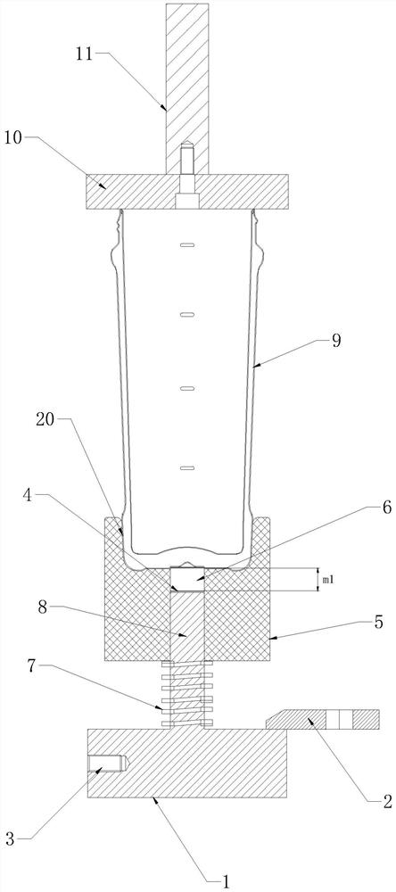
[0033]SeeFigure 1~2 In the embodiment of the present invention, a spot welding device for the bottom of a vacuum vessel includes a mold base 1, a brazing head 8 is provided on the upper end of the mold base 1, and a positioning sleeve 5 is sleeved on the outer periphery of the brazing head 8 The upper end of the positioning sleeve 5 is provided with a receiving groove 20, the upper end of the positioning sleeve 5 is provided with a second positive electrode linking copper plate 10, and the upper end of the second positive electrode linking copper plate 10 is provided with a positive electrode linking copper column 11. A product 9 is placed between the second positive electrode link copper plate 10 and the positioning sleeve 5. The positioning sleeve 5 is provided with an intermediate hole 6 for the insertion of the brazing head 8 and the brazing head 8 is located in the intermediate space and does not leak A first spring 237 is provided between the middle hole 6, the ...

Example Embodiment

[0040]Example 2

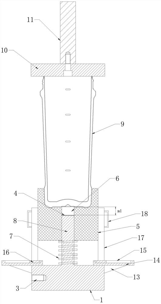
[0041]Such asFigure 3-4As shown, the difference between this embodiment and embodiment 1 is that the mold base 1 is provided with a first mounting plate 14 on both sides of the upper end, and a support is connected between the first mounting plate 14 and the mold base 1. Frame 13, the first mounting plate 14 is provided with a sliding groove 15, the sliding groove 15 is provided with a limiting plate 17, the limiting plate 17 is provided with a sliding block 16 in the sliding groove 15, the limiting A handle 18 is provided on the board 17. By providing a first mounting plate 14 on the upper end of the mold base 1, a support frame 13 is connected between the first mounting plate 14 and the mold base 1, a sliding groove 15 is provided on the first mounting plate 14, and a limiting plate 17 is provided on the sliding groove 15 , The limit plate 17 realizes the limit of the positioning sleeve 5, which effectively improves the stability of the installation of the positioni...

Example Embodiment

[0043]Example 3

[0044]Such asFigure 5 As shown, the difference between this embodiment and Embodiment 2 is that the upper end of the first mounting plate 14 is provided with a second mounting plate 21, and the second mounting plate 21 is provided with a second mounting plate 21 on the side close to the limiting plate 17. A piston 22, the side of the first piston 22 close to the limiting plate 17 is provided with a piston shaft 24, the side of the piston shaft 24 close to the limiting plate 17 is provided with a second piston 25, the second piston 25 Fixed on the limit plate 17. By providing a second mounting plate 21 on the upper end of the first mounting plate 14, a first piston 22, a piston shaft 24 and a second piston 25 are provided on the side of the second mounting plate 21 close to the limiting plate 17, and the piston shaft 24 is located on the first piston Expansion between the second piston 22 and the second piston 25, so that the piston shaft 24 can be used to expand and c...


PUM

PropertyMeasurementUnit
Depthaaaaaaaaaa

Abstract

The invention relates to a spot welding device for the bottom of a vacuum vessel. A copper welding head is arranged at the upper end of a mold base, the periphery of the copper welding head is sleevedwith a positioning sleeve, a containing groove is formed in the upper end of the positioning sleeve, a second positive electrode link copper plate is arranged above the positioning sleeve, a positiveelectrode link copper column is arranged at the upper end of the second positive electrode link copper plate, a product is placed between the second positive electrode link copper plate and the positioning sleeve, a middle hole allowing the copper welding head to be inserted therein is formed in the positioning sleeve, the copper welding head is located in the middle hole and does not leak out ofthe middle hole, a first spring is arranged between the positioning sleeve and the mode base, the first spring is connected to the periphery of the copper welding head in a sleeving mode, a first positive electrode link copper plate is arranged on one side, away from the mold base, of the copper welding head and located in the middle hole, and an electrode link screw hole is formed in the mold base. According to the spot welding device for the bottom of the vacuum vessel, the spot welding efficiency and quality are effectively improved, in addition, the positioning sleeve can be replaced according to different products, and the labor intensity is reduced.

Description

Technical field[0001]The invention relates to the technical field of welding technology, in particular to a spot welding device and welding technology at the bottom of a vacuum vessel.Background technique[0002]The current spot welding method is to take it by hand, place the solder tabs on the product, and then use a brazing head to align the solder tabs and start the spot welding machine for spot welding. The current spot welding machines on the market have the following defects: 1. The efficiency is not high, and multiple procedures are required to complete a series of actions; 2. The soldering piece is easy to be offset, and the soldering piece is easy to move when the copper welding head is placed. It is not flat after being placed, and it will cause the problem of weak welding. Therefore, it is urgent to develop a spot welding device and welding process for the bottom of the vacuum vessel to solve the problems in the prior art.Summary of the invention[0003]The purpose of the pre...

Claims


Application Information

Patent Timeline
IPC IPC(8): B23K11/11B23K11/31B23K11/36
CPCB23K11/11B23K11/314B23K11/36B23K11/362
Inventor 唐小辉陈祯力徐伟光林建
Owner 浙江安胜科技股份有限公司
Why Eureka
Try Eureka