Composite blank submerged-arc welding run-on plate without removal

A technology of composite billet and arc striking plate, applied in arc welding equipment, welding equipment, welding accessories, etc., can solve the problems of easy breakdown, inability to weld, laborious removal, etc., to improve efficiency and quality, and facilitate welding. , the effect of easy welding

Pending Publication Date: 2022-07-29
安徽金元素复合材料有限公司
View PDF0 Cites 0 Cited by
  • Summary
  • Abstract
  • Description
  • Claims
  • Application Information

AI Technical Summary

Problems solved by technology

[0003] However, for conventional submerged arc welding, every time a weld is welded, the arc strike plate needs to be welded at the two ends of the weld bead, and the arc strike plate must be removed after each weld, otherwise the next weld cannot be welded; That is: after welding a composite billet, 8 (secondary) arc starting plates need to be welded, and 8 (secondary) arc starting plates are removed. The arc starting plates made of conventional flat steel plates cannot fit the welding groove of the composite billet (vertical steel bar The distance from the edge of the steel plate is indented by 15~23mm), requiring low-current gas shielded welding to weld slowly, and the welder is laborious. Because the weld bead is thin, it is easy to be broken down during submerged arc welding
And there is no need to manually remove each weld seam with a sledgehammer and other tools. After the removal, the excess weld seam at the arc start and arc end positions of the weld seam must be removed, which is less efficient

Method used


Image

  • Composite blank submerged-arc welding run-on plate without removal
  • Composite blank submerged-arc welding run-on plate without removal
  • Composite blank submerged-arc welding run-on plate without removal

Examples


Embodiment Construction

[0020] In order to make it easy to understand the technical means, creation features, achieved goals and effects of the present invention, the present invention will be further described below with reference to the specific embodiments.

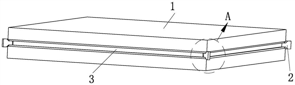
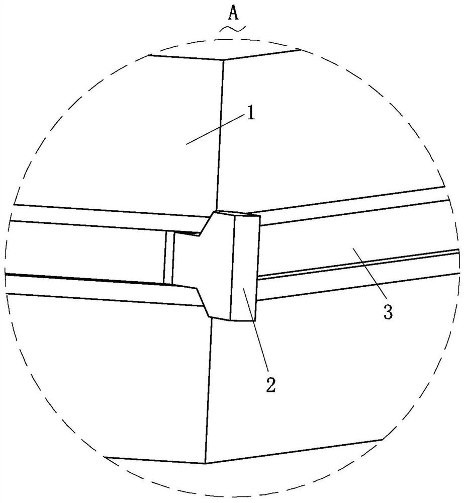
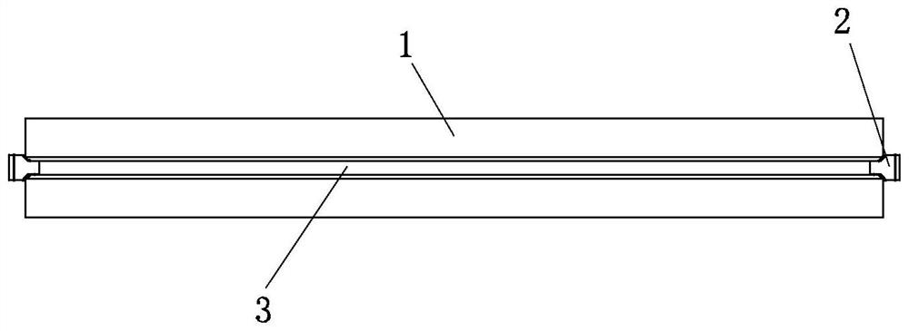
[0021] like Figure 1-Figure 6 As shown in the figure, a composite slab submerged arc welding-free removal arc ignition plate according to the present invention includes two composite blank steel plates 2, and the four corners of the two composite blank steel plates 2 are provided with a removal-free arc ignition plate 1. Four composite billet steel vertical bars 3 are arranged between the composite billet steel plates 2, and a slope 5 is provided on the removal-free arc striking plate 1, and the slope surface 5 is welded with the composite billet steel plate 2. The arc striking plate 1 is provided with a positioning groove 4, and two adjacent composite billet steel vertical bars 3 are welded in the same positioning groove 4; It's the next f...


PUM


Abstract

The invention relates to the technical field of run-on plates, in particular to a composite blank submerged-arc welding removal-free run-on plate which comprises two composite blank steel plates, removal-free run-on plates are arranged at the four corners of the two composite blank steel plates, four composite blank steel vertical strips are arranged between the two composite blank steel plates, slope surfaces are arranged on the removal-free run-on plates, and the composite blank steel vertical strips are arranged on the slope surfaces. The slope surface is welded with the composite blank steel plate, a positioning groove is not formed in the run-on plate, and two adjacent composite blank steel vertical strips are welded in the same positioning groove; the run-on plate is not removed, namely the run-on plate is used for the submerged-arc welding, and the run-off plate is also used for the next run-off plate; only four removal-free end tabs need to be welded and do not need to be removed, due to the fact that the slope faces of the removal-free end tabs are completely attached to the welding groove of the composite blank in shape, a submerged-arc welding welder can conduct tack welding easily, welding of the removal-free end tabs is more convenient and rapid, due to the fact that removal is not needed, the four removal-free end tabs can be welded at a time, and the welding efficiency is improved. Submerged-arc welding becomes one part of a welding bead after being welded, so that worry and labor are saved, and the efficiency is improved.

Description

technical field [0001] The invention relates to the technical field of arc striking plates, in particular to a composite blank submerged arc welding without removing the arc striking plate. Background technique [0002] The traditional composite billet is made of two carbon steel plates up and down, two stainless steel plates are placed in the middle, and the stainless steel is isolated by vertical steel bars around the carbon steel plates. When making the billet, it is necessary to carry out sealed submerged arc welding on the surrounding and vertical steel bars of the upper and lower carbon steel plates of the composite billet. Arc plate), otherwise it is easy to produce unacceptable welding defects such as porosity, unfusion, arc crater, breakdown and so on at the arc starting and arc ending. [0003] However, in conventional submerged arc welding, it is necessary to weld the arc pilot plate at the two ends of the weld bead for each welding pass, and the arc pilot plate ...

Claims


Application Information

Patent Timeline
IPC IPC(8): B23K9/067B23K9/18B23K9/32
CPCB23K9/18B23K9/067B23K9/32
Inventor 陈兵傅广兵傅广华杨果煜周燕张启林
Owner 安徽金元素复合材料有限公司
Why Eureka
Try Eureka