Flow rate control mechanism, flow rate control method and automatic loading and sequencing device

A technology of flow rate control and frame, which is applied in the field of medical equipment, can solve the problems of occasional hollows, large resistance, and crushed items in the silo, and achieve the effect of smooth operation

Pending Publication Date: 2021-02-09
ZYBIO INC
View PDF0 Cites 3 Cited by
  • Summary
  • Abstract
  • Description
  • Claims
  • Application Information

AI Technical Summary

Problems solved by technology

[0003] In the silo, the bottom of the silo usually has an inclined guide plate, so that the items will flow to the target position at the bottom of the silo under the action of its own weight. Stuck accumulation, resulting in occasional voids in the lower part of the silo, especially for odd-shaped items (e.g., Figure 10 This phenomenon is more likely to occur; in addition, in some devices, the items at the bottom of the silo are ejected to the next station in a bottom-up manner. If there are too many items at the bottom of the silo , the jacking parts used to lift the items have high resistance during the rising process, which may crush the items, or may be stuck during the rising process

Method used


Image

  • Flow rate control mechanism, flow rate control method and automatic loading and sequencing device
  • Flow rate control mechanism, flow rate control method and automatic loading and sequencing device
  • Flow rate control mechanism, flow rate control method and automatic loading and sequencing device

Examples


Embodiment Construction

[0045] In the following description, numerous specific details are set forth in order to provide a more thorough understanding of the present invention. It will be apparent, however, to one skilled in the art that the present invention may be practiced without one or more of these details. In other instances, some technical features known in the art have not been described in order to avoid obscuring the present invention.

[0046] It should be understood that the present invention may be embodied in different forms and should not be construed as limited to the embodiments set forth herein. Rather, these embodiments are provided so that this disclosure will be thorough and complete, and will fully convey the scope of the invention to those skilled in the art. In the drawings, the same reference numerals refer to the same components throughout.

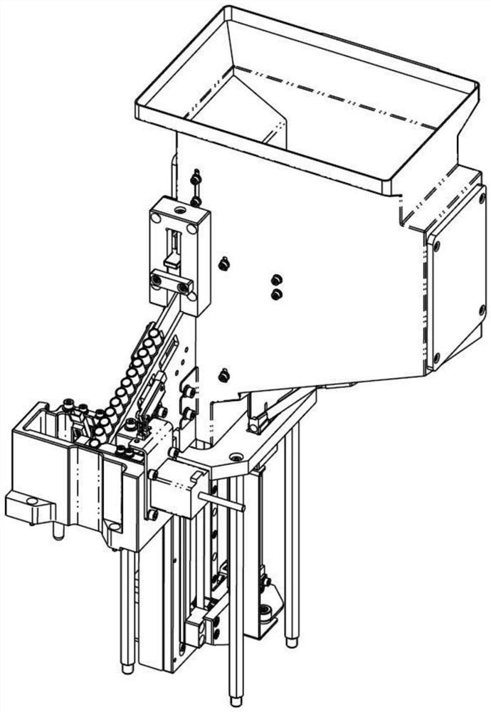
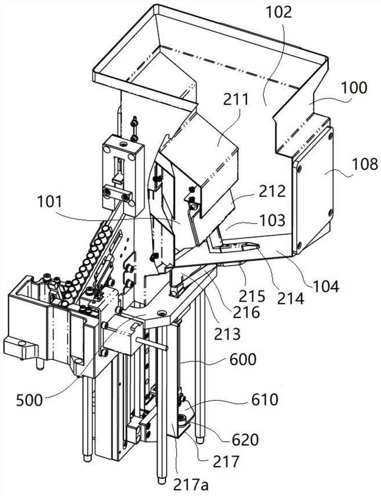
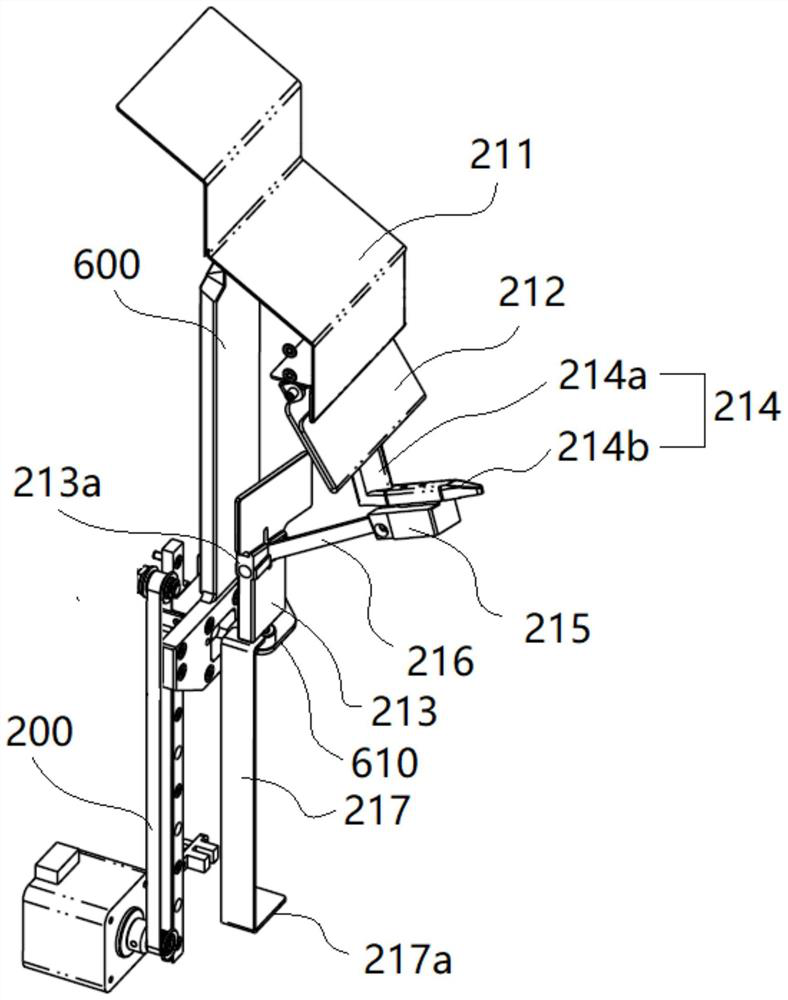
[0047] The items in the silo in each of the following embodiments are all taking the reaction cup as an example. see in combinatio...


PUM


Abstract

The invention discloses a flow rate control mechanism, a flow rate control method and an automatic loading and sequencing device. The flow rate control mechanism and the flow rate control method divide the space in a stock bin into a buffer area and an isolation area, and a stroke between the buffer area and the isolation area allows articles to enter a channel of the buffer area from the isolation area. A reciprocating moving part changes the boundary position of the isolation area through periodic reciprocating motion, repeatedly reduces or expands the volume of the isolation area, and pushes, squeezes and disturbs articles in the isolation area when the volume of the isolation area is reduced. According to the flow rate control mechanism, the number of articles in the buffer area is relatively small, so that smooth operation of a material ejecting piece is facilitated, and the articles are not easily damaged by extrusion; and through the reciprocating motion of the reciprocating moving part, the boundary position of the isolation area is changed, articles in the isolation area are pushed, squeezed and disturbed, the phenomenon that a reaction cup is stuck or hollow in a bin canbe avoided, and the reaction cup can enter the buffer area at the periodically-changed flow speed, the reaction cup flows into the bottommost part of the bin at a constant speed equivalently.

Description

technical field [0001] The invention relates to medical equipment, in particular to a flow rate control mechanism, a flow rate control method and an automatic loading and sorting device. Background technique [0002] In order to improve convenience, many items (for example, reaction vessels) are often stacked in a silo in an out-of-order state, and then sent to other devices one by one for sorting. [0003] In the silo, the bottom of the silo usually has an inclined guide plate, so that the items flow to the target position at the bottom of the silo by their own weight. Buildup stuck, resulting in occasional voids in the lower part of the silo, especially for odd-shaped items (e.g., Figure 10 In addition, in some devices, the bottom-up method is used to push out the items at the bottom of the bin to the next station. If there are too many items at the bottom of the bin , The top material used to lift the item has a large resistance during the rising process, which may sque...

Claims


Application Information

Patent Timeline
Patent Type & Authority Applications(China)
IPC IPC(8): B65G65/44B65G47/26
CPCB65G47/26B65G65/44
Inventor 曹胜邓卫平
Owner ZYBIO INC
Why Eureka
Try Eureka