
Special trolley for replacing current transformer of armored switch cabinet

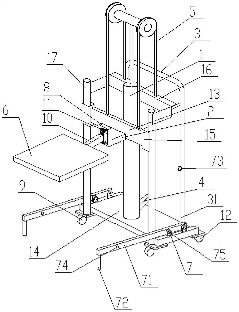
A technology for current transformers and switchgears, which is applied in the field of special trolleys for the replacement of current transformers in armored switchgears. It can solve the problems of unguaranteed power supply reliability, unsatisfied power supply reliability, and low construction efficiency, so as to improve the replacement work. Efficiency, reliable design principles, and the effect of saving manpower and material resources

Inactive Publication Date: 2021-02-09
国网山东省电力公司东平县供电公司 +2
View PDF6 Cites 1 Cited by
  • Summary
  • Abstract
  • Description
  • Claims
  • Application Information

AI Technical Summary

Problems solved by technology

[0002] At present, the traditional current transformer replacement tool cannot realize the lifting function and the horizontal rotation movement at the same time, and the flexibility is poor
The entire construction time is long, and the corresponding power outage time is relatively long, which does not meet the current requirements for improving power supply reliability and improving customers' sense of gain in power usage
Therefore, the efficiency of construction work is low, the required power outage time is long, and the reliability requirements of power supply cannot be guaranteed.

Method used


Image

  • Special trolley for replacing current transformer of armored switch cabinet
  • Special trolley for replacing current transformer of armored switch cabinet

Examples


Embodiment Construction

[0018] In order to enable those skilled in the art to better understand the technical solutions in the present invention, the technical solutions in the embodiments of the present invention will be clearly and completely described below in conjunction with the drawings in the embodiments of the present invention. Obviously, the described The embodiments are only some of the embodiments of the present invention, not all of them. Based on the embodiments of the present invention, all other embodiments obtained by persons of ordinary skill in the art without making creative efforts shall fall within the protection scope of the present invention.

[0019] Key terms appearing in the embodiments of the present invention are explained below.

[0020] In the description of the present invention, it should be understood that the orientation or positional relationship indicated by the terms "upper", "lower", "front", "rear", "left", "right" etc. The orientation or positional relationsh...


PUM


Abstract

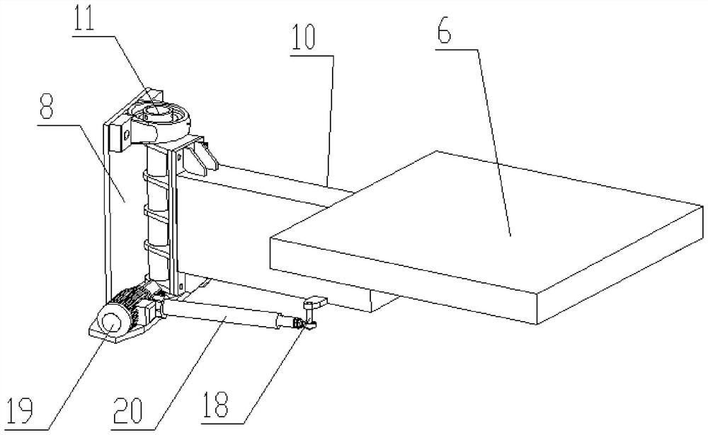
The invention discloses a special trolley for replacing a current transformer of an armored switch cabinet. The trolley comprises a device frame body, a moving system, a supporting system and a lifting system, wherein stand columns are fixedly arranged at the two sides of the front end of a bottom frame correspondingly, the tops of the two stand columns are connected through a chain fixing plate,a transportation handle is fixedly arranged at the top of the rear end of the bottom frame, and anti-overturning components are arranged at the two sides of the bottom frame correspondingly; transportation rear wheels are arranged at the two sides of the bottom of the rear end of the bottom frame, and pulley brakes are arranged on the transportation rear wheels; and the supporting system comprisesa stepped transition platform fixedly connected to a sliding plate, a connecting rod is rotationally connected to the front end of the stepped transition platform through a vertically-arranged firstrotating shaft, a supporting platform is fixed to the end of the connecting rod, a motor is fixed to the position, located at one side of the connecting rod, of the stepped transition platform, the motor is connected to the fixed end of an electric telescopic rod, and the extending end of the electric telescopic rod is rotationally connected to the connecting rod through a second rotating shaft. Through the rotary supporting system and the lifting system, the movement in the horizontal direction and the vertical direction can be automatically achieved.

Description

technical field [0001] The invention relates to the technical field of tools for replacing current transformers in armored switch cabinets, in particular to a special trolley for replacing current transformers in armored switch cabinets. Background technique [0002] At present, the traditional current transformer replacement tool cannot realize the lifting function and simultaneously rotate and move in the horizontal direction, and the flexibility is poor. The entire construction work takes a long time, and the corresponding power outage time is relatively long, which does not meet the current requirements for improving power supply reliability and improving customers' sense of gain in power usage. Therefore, the efficiency of construction work is low, the required power outage time is long, and the reliability requirements of power supply cannot be guaranteed. [0003] In order to overcome the deficiencies in the above-mentioned prior art, the present invention provides a...

Claims


Application Information

Patent Timeline
Patent Type & Authority Applications(China)
IPC IPC(8): B66F9/06B66F9/12B66F9/14B66F9/22B66F9/24B66F9/08B66F9/075
CPCB66F9/06B66F9/127B66F9/14B66F9/22B66F9/24B66F9/07509B66F9/07559B66F9/08B66F9/07504B66F9/0755
Inventor 孙启健郭龙龙尹超宿默如张涛张锦迎刘峰张楠刘忠民王明伟田莉莉黄凤英
Owner 国网山东省电力公司东平县供电公司
Learn More