
Infrared continuous zooming optical system based on composite zooming and having super-large zoom ratio

An optical system and variable magnification technology, applied in the optical field, can solve the problems of large lens size and low optical transmittance, achieve high optical transmittance, clear imaging, and facilitate the detection of long-distance weak radiation targets

Pending Publication Date: 2021-02-09
HUBEI JIUZHIYANG INFRARED SYST CO LTD
View PDF0 Cites 0 Cited by
  • Summary
  • Abstract
  • Description
  • Claims
  • Application Information

AI Technical Summary

Problems solved by technology

[0004] Aiming at the design of the super-large zoom ratio continuous zoom optical system in the prior art, if the traditional continuous zoom design method is adopted, problems such as large lens size and low optical transmittance will be faced. The present invention provides a super large zoom ratio continuous zoom Compact and miniaturized infrared continuous zoom optical system based on compound zoom with super large zoom ratio

Method used


Image

  • Infrared continuous zooming optical system based on composite zooming and having super-large zoom ratio
  • Infrared continuous zooming optical system based on composite zooming and having super-large zoom ratio
  • Infrared continuous zooming optical system based on composite zooming and having super-large zoom ratio

Examples


Embodiment Construction

[0028] In order to make the object, technical solution and advantages of the present invention clearer, the present invention will be further described in detail below in conjunction with the accompanying drawings and embodiments. It should be understood that the specific embodiments described here are only used to explain the present invention, not to limit the present invention.

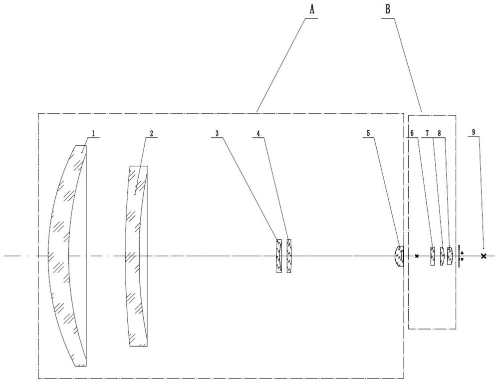
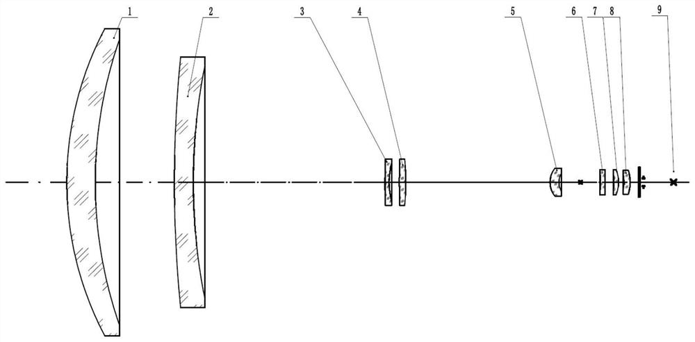
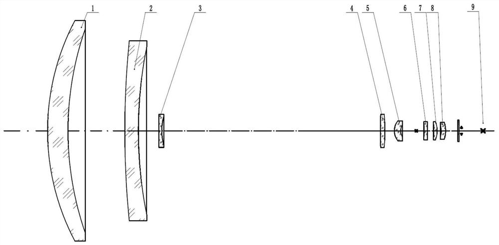
[0029] like Figure 1-Figure 3 As shown, the infrared continuous zoom optical system based on the compound zoom ultra-large zoom ratio in the embodiment of the present invention has sequentially from the object side to the image side along the optical axis: a continuous zoom group A and a two-stage zoom group B; Zoom group A includes main objective lens group 1, secondary objective lens group 2, primary zoom group 3, compensation group 4, fixed group 5; secondary zoom group B includes first rear group lens 6, second rear group lens 7 and The third rear lens group 8 . The primary zoom group 3 is m...


PUM


Abstract

The invention discloses an infrared continuous zooming optical system based on composite zooming and having an ultra-large zoom ratio. The infrared continuous zooming optical system sequentially comprises a continuous zooming group and a secondary zooming group from an object space to an image space along an optical axis direction; the continuous zooming group sequentially comprises a main objective lens group, a secondary objective lens group, a primary zooming group, a compensation group and a fixed group from an object side to an image side along the optical axis direction; the secondary zooming group sequentially comprises a first rear group lens, a second rear group lens and a third rear group lens from the object side to the image side along the optical axis direction; when the primary zooming group is farthest from the compensation group, the optical system is in a short focus state; when the primary zooming group is closest to the compensation group, the optical system is in along focus state; the light beam from the object side is converged between the fixed group and the first rear group lens through the continuous zooming group; and the first rear group lens, the secondrear group lens and the third rear group lens are used for finally imaging an image formed by the continuous zooming group on the target surface of the detector. The ultra-large zoom ratio continuouszooming compact miniaturization design is adopted, the system image quality is good, and the imaging is clear.

Description

technical field [0001] The invention relates to the field of optics, in particular to an infrared continuous zoom optical system based on a compound zoom super large zoom ratio. Background technique [0002] In recent years, infrared thermal imaging technology has developed rapidly. Due to its many excellent features, such as passive reception of infrared radiation, high concealment, and no electronic interference by the enemy; high precision; easy-to-observe images, it is widely used in military, vehicle, Temperature measurement, power line inspection, border security and other fields have been widely used, especially in the military field. The infrared optical system is an important part of the infrared thermal imager by collecting the external infrared radiation and finally focusing it on the target surface of the detector. Infrared optical systems can be roughly divided into fixed focus, two-speed, multi-speed and continuous zoom. The continuous zoom optical system can...

Claims


Application Information

Patent Timeline
IPC IPC(8): G02B15/14G02B15/15G02B1/02G02B5/18
CPCG02B15/146G02B15/15G02B1/02G02B5/1814
Inventor 李武李忠熊涛李勇吴学鹏
Owner HUBEI JIUZHIYANG INFRARED SYST CO LTD
Learn More