
Image sensor, camera module and terminal equipment

An image sensor and image-side technology, applied in image communication, instruments, televisions, etc., can solve problems such as screen shadows, chief ray angle matching, and affecting image brightness uniformity

Active Publication Date: 2022-05-17
GUANGDONG OPPO MOBILE TELECOMM CORP LTD
View PDF7 Cites 0 Cited by
  • Summary
  • Abstract
  • Description
  • Claims
  • Application Information

AI Technical Summary

Problems solved by technology

But for the lens with continuous zoom function, the change of the lens from long focus to short focus will cause the chief ray angle (CRA) to gradually increase, but because the chief ray angle of the microlens on the image sensor is fixed at this time, it cannot be compared with The main ray angle after the lens change matches, so it is easy to cause shadows in the picture and affect the brightness uniformity of the image

Method used


Image

  • Image sensor, camera module and terminal equipment
  • Image sensor, camera module and terminal equipment
  • Image sensor, camera module and terminal equipment

Examples


Embodiment Construction

[0036] In order to facilitate the understanding of the present application, the present application will be described more fully below with reference to the relevant drawings. Preferred embodiments of the application are shown in the accompanying drawings. However, the present application can be embodied in many different forms and is not limited to the embodiments described herein. On the contrary, the purpose of providing these embodiments is to make the understanding of the disclosure of the application more thorough and comprehensive.

[0037] As used herein, "terminal equipment" refers to a device capable of receiving and / or sending communication signals, including but not limited to, connected via any one or several of the following connection methods:

[0038] (1) Connection via wired lines, such as public switched telephone network (Public Switched Telephone Networks, PSTN), digital subscriber line (Digital Subscriber Line, DSL), digital cable, direct cable connection...


PUM


Abstract

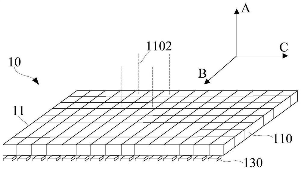
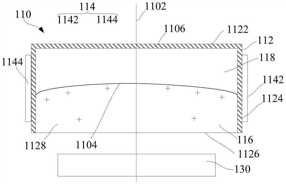
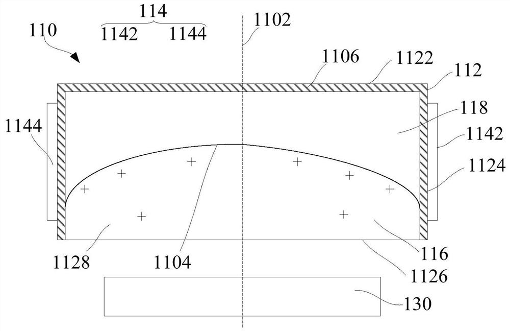
The application relates to an image sensor, a camera module and a terminal device. The image sensor includes: an optical array, including a plurality of optical elements arranged in an array, the optical elements include a housing, electrodes, a first liquid and a second liquid, the electrodes are fixed relative to the housing, the housing is provided with a cavity, and the electrodes can be placed in the air. An electric field is formed in the cavity, the first liquid and the second liquid are arranged in the cavity immiscibly, the first liquid and the second liquid are respectively transparent liquids, and a refraction interface is formed between the first liquid and the second liquid, and the electrodes can Drive at least one of the first liquid and the second liquid to change the curvature of the refraction interface; and a receiving array, including a plurality of receiving units arranged in an array, any optical element corresponding to at least one receiving unit along the optical axis direction, receiving The unit is used to receive light passing through the optical element. The above-mentioned optical elements can adjust the chief ray angle to match the chief ray angle of the zoom lens group, so as to improve the imaging quality.

Description

technical field [0001] The present application relates to the field of electronic equipment, in particular to an image sensor, camera module and terminal equipment. Background technique [0002] For a traditional image sensor, a microlens array is arranged on the side of the receiving surface to focus the incident light, thereby improving the photoelectric conversion efficiency of the photodiode. But for the lens with continuous zoom function, the change of the lens from long focus to short focus will cause the chief ray angle (CRA) to gradually increase, but because the chief ray angle of the microlens on the image sensor is fixed at this time, it cannot be compared with The main ray angle after the lens change matches, so it is easy to cause shadows in the picture and affect the brightness uniformity of the image. Contents of the invention [0003] Embodiments of the present application provide an image sensor capable of adjusting a chief ray angle, a camera module, and...

Claims


Application Information

Patent Timeline
Patent Type & Authority Patents(China)
IPC IPC(8): G02B26/00H04N5/225
CPCG02B26/005H04N23/55
Inventor 贾玉虎
Owner GUANGDONG OPPO MOBILE TELECOMM CORP LTD
Learn More