Device binding method, apparatus and equipment
A device, binding technology, used in instrumentation, nonlinear optics, optics, etc.
- Summary
- Abstract
- Description
- Claims
- Application Information
AI Technical Summary
Problems solved by technology
Method used
Image


Examples
Embodiment 1
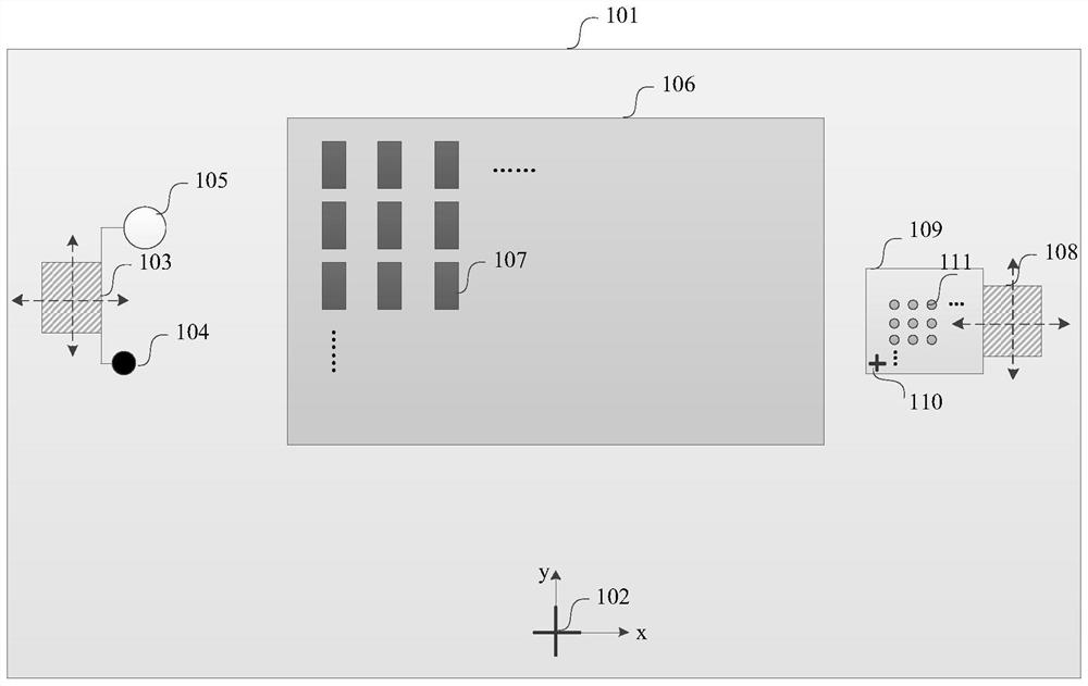
[0127] Such as figure 1 As shown, the embodiment of the present invention provides an application scenario for device binding. The above application scenario is only an example of an application scenario for device binding, and is not limited. In specific implementation, it can be used in the above application Add or delete some components in the scene, including:
[0128] The first workbench 101 is used to carry the substrate, and the first origin of the marking pattern is fixed on the first workbench.
[0129] The first origin 102 is fixed on the above-mentioned first workbench, and is used to determine the origin of the equipment.
[0130] The first movement group 103 is integrated with the binding head and the camera and has a fixed relative positional relationship, which can move in the X and Y directions and drive the binding head and the camera to move.
[0131] The binding head 104 has a fixed relative position relationship with the above-mentioned first movement gro...
Embodiment approach 1
[0209] Embodiment 1: Obtain the deviation of all bound devices relative to the camera by taking pictures with the camera and record the axis coordinates of the second motion group to calibrate the relationship between the device coordinates of the bound devices and the device coordinates of the second origin.
[0210] Move the first movement group and the second movement group so that the camera is basically above the second movement group, and control the camera to move in the vertical direction to ensure that the camera can clearly see the second workbench;
[0211] Move the second motion group so that the center of the camera's field of view coincides with the center of the second origin, and record the axis coordinates of the second motion group at this time as (X2_d0, Y2_d0);
[0212] Move the second movement group in turn, so that the bound device on the second workbench appears in the center of the camera's field of view, and the camera takes pictures to obtain the devia...
Embodiment approach 2
[0218] Embodiment 2: Obtain the deviation of all bound devices relative to the camera by taking pictures with the camera and record the axis coordinates of the second motion group to calibrate the relationship between the device coordinates of the bound devices and the device coordinates of the second origin.
[0219] Move the first movement group and the second movement group so that the camera is basically above the second movement group, and control the camera to move in the vertical direction to ensure that the camera can clearly see the second workbench;
[0220] Move the second motion group so that the center of the camera's field of view coincides with the center of the second origin, and record the axis coordinates of the first motion group at this time as (X1_d0, Y1_d0);
[0221] Move the first movement group in turn, so that the bound device on the second workbench appears in the center of the camera's field of view, and the camera takes pictures to obtain the deviati...
PUM
 Abstract
Description
Claims
Application Information
 - R&D
- Intellectual Property
- Life Sciences
- Materials
- Tech Scout
- Unparalleled Data Quality
- Higher Quality Content
- 60% Fewer Hallucinations
Browse by: Latest US Patents, China's latest patents, Technical Efficacy Thesaurus, Application Domain, Technology Topic, Popular Technical Reports.
© 2025 PatSnap. All rights reserved.Legal|Privacy policy|Modern Slavery Act Transparency Statement|Sitemap|About US| Contact US: help@patsnap.com