
A cable fixing device

A technology for fixing devices and cables, applied in the direction of electrical components, etc., can solve the problems of troublesome maintenance, no layers, and cables are easily confused, and achieve the effect of easy maintenance.

Active Publication Date: 2022-04-12
GUANGDONG POWER GRID CO LTD +1
View PDF8 Cites 0 Cited by
  • Summary
  • Abstract
  • Description
  • Claims
  • Application Information

AI Technical Summary

Problems solved by technology

[0003] When power equipment is used for power transmission, it is necessary to use cables to connect and then supply power to the power equipment. In this way, the cables need to be laid and fixed, especially when the cables of the equipment in the factory are laid, they are generally installed on the side of the wall of the house. Upper support rods, etc., and then use some insulating clamping equipment on the support rods to clamp and fix the cables, but the cable fixing devices are all rigid structures, and when the cables are subjected to external forces, they are easily deformed
Moreover, the arrangement of the cables is prone to confusion and lack of hierarchy. When fixing cables of different diameters, different cable fixing devices are required to fix them, which makes it more troublesome to install and fix the cables. When fixing, the entire strand needs to be fixed and installed. The current cable fixing device generally places the entire strand of cable directly on the support frame, and then uses the fixed cover to fix the entire strand of cable. a lot of trouble

Method used

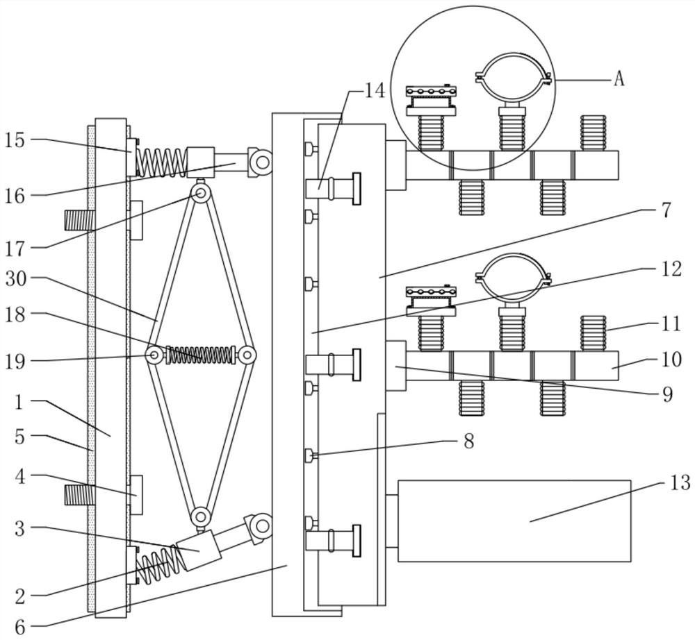
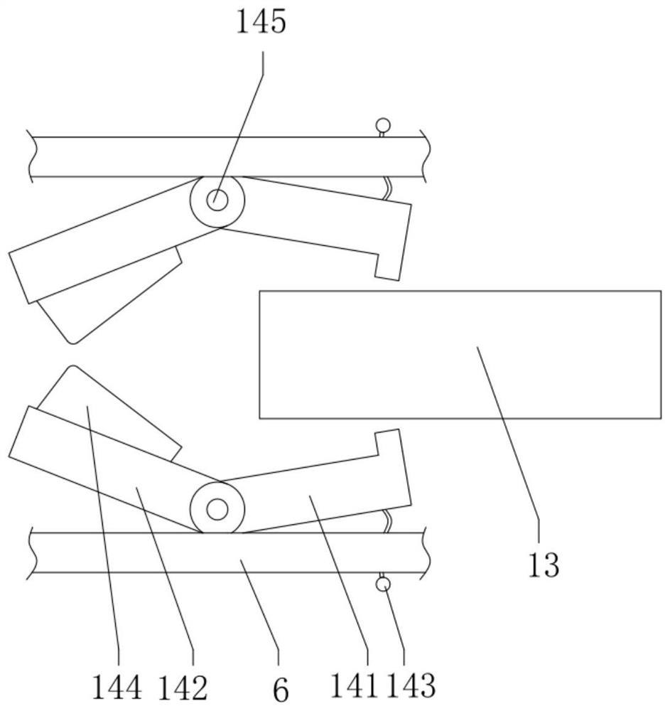
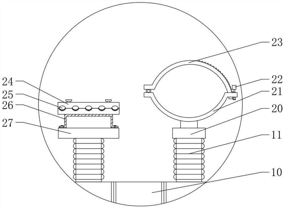

Image

  • A cable fixing device
  • A cable fixing device
  • A cable fixing device

Examples


Embodiment Construction

[0044] The technical solutions of the present invention will be further described below in conjunction with the accompanying drawings and embodiments. It should be understood that the specific embodiments described here are only used to explain the present invention, but not to limit the present invention. In addition, it should be noted that, for the convenience of description, only the parts related to the present invention are shown in the drawings but not all of them.

[0045] In the description of the present invention, it should be noted that unless otherwise specified and limited, the terms "installation", "connection" and "connection" should be understood in a broad sense, for example, it can be a fixed connection or a detachable connection. Connection; it can be a mechanical connection or an electrical connection; it can be a direct connection or an indirect connection through an intermediary, and it can be the internal communication of two components. Those of ordin...


PUM


Abstract

The present invention relates to the technical field of power auxiliary equipment, in particular to a cable fixing device, which comprises a first connecting plate, a cable clamp seat, a first tension spring, a stranded cable clamp and a single cable clamp, wherein the first connecting plate is fixed on the On the wall, one end of the first tension spring is fixedly connected to the first connecting plate, and the other end is rotatably connected to the cable holder. , The single cable clamp is fixedly connected with the cable clamp base, and the single cable clamp is used to clamp a single cable. When the cable is affected by external force, the external force is transmitted to the stranded cable clamp or single cable clamp holding the cable, the cable clamp base and the first tension spring in turn. The first tension spring can deform under the action of the external force, thus avoiding the external force. In the case of direct damage to the cables, the cables with different diameters can be clamped by the cable clamps, and the cables can be placed in an orderly manner with a single cable clamp, which is convenient for later maintenance.

Description

technical field [0001] The invention relates to the technical field of electric power auxiliary equipment, in particular to a cable fixing device. Background technique [0002] Power equipment mainly includes power generation equipment and power supply equipment. Power generation equipment is mainly power plant boilers, steam turbines, gas turbines, water turbines, generators, etc. Power supply equipment is mainly transmission lines of various voltage levels, transformers, contactors, etc. Etc., the cable is an indispensable power transmission device for connecting power equipment. [0003] When power equipment is used for power transmission, it is necessary to use cables to connect and then supply power to the power equipment. In this way, the cables need to be laid and fixed, especially when the cables of the equipment in the factory are laid, they are generally installed on the side of the wall of the house. Upper support rods, etc., and then use some insulating clamping...

Claims


Application Information

Patent Timeline
Patent Type & Authority Patents(China)
IPC IPC(8): H02G3/32H02G3/04
CPCH02G3/32H02G3/0456
Inventor 黄鑫王志坚陈卓云魏立武罗建文
Owner GUANGDONG POWER GRID CO LTD
Learn More