
Design method of rope-driven micro-instrument external force indirect detection model

A rope-driven, detection model technology, applied in surgical manipulators, surgical robots, computer-aided surgery, etc., can solve problems such as errors, low external force detection accuracy, and hysteresis effects.

Active Publication Date: 2021-02-12
XI'AN POLYTECHNIC UNIVERSITY
View PDF5 Cites 2 Cited by
  • Summary
  • Abstract
  • Description
  • Claims
  • Application Information

AI Technical Summary

Problems solved by technology

The existing force detection capabilities of surgical robots are mainly divided into two types: direct detection and indirect detection. Considering the influence of the disinfection method of surgical micro-instruments and the properties of consumables, it is difficult to apply the direct detection method in actual surgery, while the existing indirect Most of the detection methods are indirectly estimated by the driving current or the system model. Due to the influence of current resolution and hysteresis effects, the accuracy of external force detection is not high, especially when the system starts and stops, there are large errors and hysteresis effects.
The method of model estimation usually ignores the influence of nonlinear factors such as clearance and friction, and the simplification or linearization of the model leads to low detection accuracy of external force of rope-driven micro-device

Method used

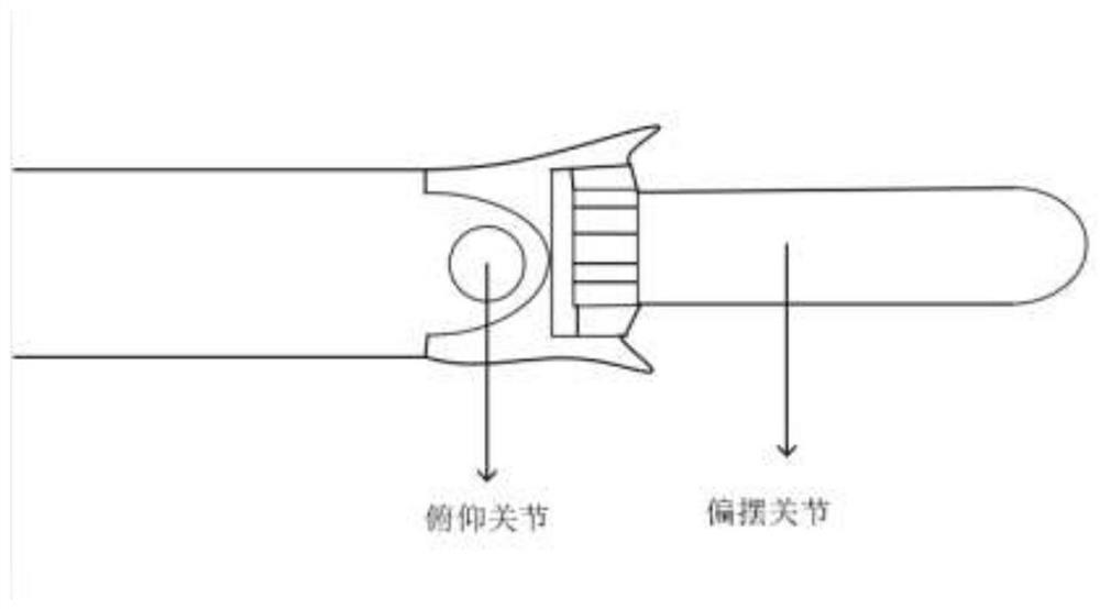
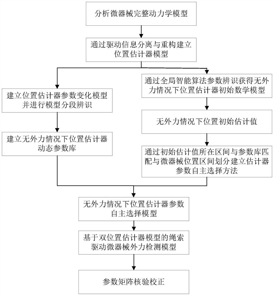
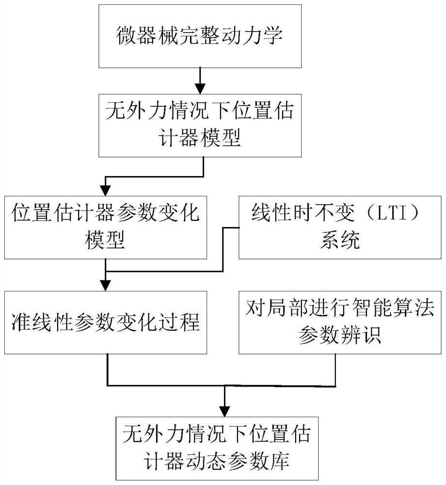

Image

  • Design method of rope-driven micro-instrument external force indirect detection model
  • Design method of rope-driven micro-instrument external force indirect detection model
  • Design method of rope-driven micro-instrument external force indirect detection model

Examples


Embodiment Construction

[0064] The present invention will be described in detail below in conjunction with the accompanying drawings and specific embodiments.

[0065] The invention provides a design method for the indirect detection model of the external force of the rope-driven micro-device, such as figure 2 shown, including the following steps:

[0066] Step 1. Complete dynamic modeling of the rope-driven micro-device system;

[0067] Step 2. Based on the complete dynamic model of the micro-device, establish a position estimator model and a position estimator parameter change model under the condition of no external force;

[0068] Step 3. Segmentally identify the model of the micro-device position estimator without external force, and establish a dynamic parameter library of the micro-device position estimator without external force;

[0069] Step 4, establishing a parameter autonomous selection model of the micro-device position estimator under the condition of no external force;

[0070] St...


PUM


Abstract

The invention discloses a design method of a rope-driven micro-instrument external force indirect detection model. The design method comprises the following steps: establishing a rope-driven micro-instrument system complete kinetic model; establishing a micro-instrument position estimator and a parameter change model thereof under the condition of no external force on the basis of the complete kinetic model of the micro-instrument system; carrying out segmented identification on the micro-instrument position estimator model under the condition of no external force, and establishing a dynamic parameter library of the micro-instrument position estimator under the condition of no external force; establishing a parameter autonomous selection model of the micro instrument position estimator under the condition of no external force; the difference between the output of the micro-instrument position estimator parameter autonomous selection model under the condition of no external force and the position estimation value output by the micro-instrument system complete kinetic model under the condition of external force is calculated, and the difference value is regarded as disturbance causedby the external force to establish a rope-driven micro-instrument external force indirect detection model. The detection model obtained by the design method greatly improves the detection accuracy ofthe external force of the rope-driven micro instrument.

Description

technical field [0001] The invention belongs to the technical field of minimally invasive surgical robots, and in particular relates to a design method for an indirect detection model of external force of a rope-driven micro-device. Background technique [0002] The external force detection capability of micro-device is the basis for the realization of force perception and force feedback of surgical robots, which helps doctors perceive and apply the correct surgical operation force, increasing the sense of presence. The existing force detection capabilities of surgical robots are mainly divided into two types: direct detection and indirect detection. Considering the influence of the disinfection method of surgical micro-instruments and the properties of consumables, it is difficult to apply the direct detection method in actual surgery, while the existing indirect Most of the detection methods are indirectly estimated by the driving current or the system model. Due to the in...

Claims


Application Information

Patent Timeline
IPC IPC(8): A61B34/00A61B34/30
CPCA61B34/30A61B34/76
Inventor 王文杰陈聪聪曹玉婷麻健伟王晓华张蕾张凯兵
Owner XI'AN POLYTECHNIC UNIVERSITY
Learn More