Supercharge Your Innovation With Domain-Expert AI Agents!

Paint spraying device for new energy automobile charging pile production

A technology for new energy vehicles and charging piles, which is applied in the field of sheet metal processing and can solve the problems of clamping and clamping difficult sheet metal parts.

Active Publication Date: 2021-02-12
合肥龙智机电科技有限公司
View PDF7 Cites 4 Cited by
  • Summary
  • Abstract
  • Description
  • Claims
  • Application Information

AI Technical Summary

Problems solved by technology

It is difficult for the existing paint spraying device to clamp the bent sheet metal and spray paint in all directions

Method used


Image

  • Paint spraying device for new energy automobile charging pile production
  • Paint spraying device for new energy automobile charging pile production
  • Paint spraying device for new energy automobile charging pile production

Examples


Embodiment 1

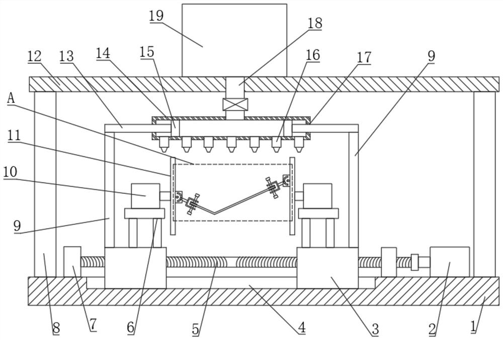
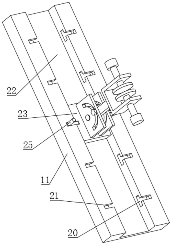
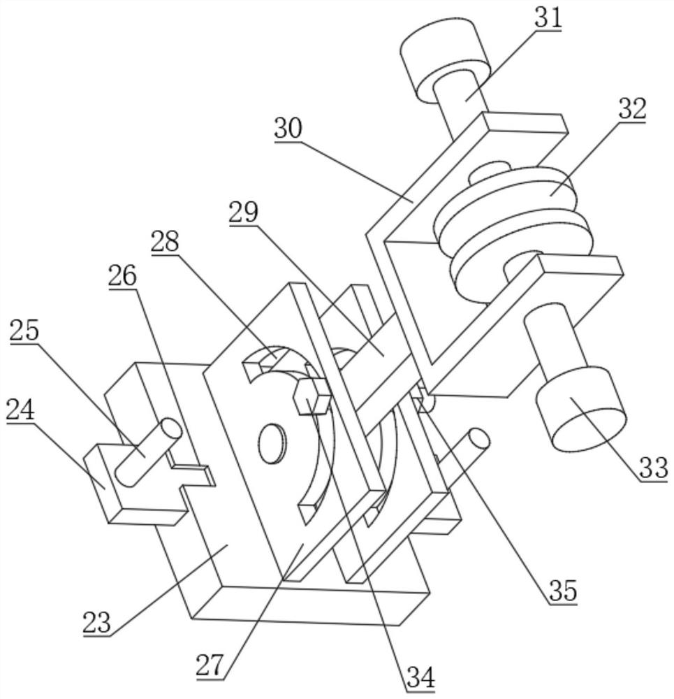
[0026] see Figure 1 to Figure 5 , a painting device for the production of new energy vehicle charging piles, comprising a base 1 and a top plate 12, the base 1 is equipped with a motor 2, the upper surface of the base 1 is provided with a chute 4, and the chute 4 is slidably connected with Two moving seats 3, the moving seat 3 is provided with a threaded through hole 1, the threaded through hole 1 is connected with a threaded shaft 5, the threaded shaft 5 is connected with the output shaft of the motor one 2, and the moving seat 3 is equipped with a motor two 10 , the output shaft of the motor two 10 is connected with a rotating plate 11, the rotating plate 11 is provided with a groove one 22, and several grooves two 20 are arranged on the left and right sides of the groove one 22, and the top of the groove two 20 Rectangular through groove one 21 is arranged on the surface, in the groove one 22 sliding fit is connected with moving plate 23, and the left and right side of mov...

Embodiment 2

[0031] see Figure 1 to Figure 5 , this embodiment is a further description of the painting device for the production of a new energy vehicle charging pile described in specific example 1. In this embodiment, two pistons 15 are arranged inside the shunt pipe 14, and two pistons 15 are arranged on the piston 15. Fixedly connected with a piston rod 13, the left end surface and the right end surface of the shunt pipe 14 are all provided with a through hole 17, the piston rod 13 runs through the through hole 17, and the side of the piston rod 13 slides with the inner wall of the through hole 17 Mate connection.

[0032] The upper surface of the moving base 3 is fixedly connected with a support column 9, and the upper end of the support column 9 is fixedly connected with the piston rod 13. The number of the piston 15, the piston rod 13 and the support column 9 are two and are all about the shunt tube. The symmetry plane of 14 is symmetrically arranged left and right, and the side ...


PUM


Abstract

The invention discloses a paint spraying device for new energy automobile charging pile production. The paint spraying device for new energy automobile charging pile production comprises a base and atop plate, wherein a first motor is installed on the base; a sliding groove is formed in the upper surface of the base; two movable bases are connected into the sliding groove in a sliding fit mode; first threaded through holes are formed in the movable bases; threaded shafts are connected to the first threaded through holes in a matched mode; the threaded shafts are connected with an output shaftof the first motor; second motors are installed on the movable bases; rotating plates are connected onto output shafts of the second motors; first grooves are formed in the rotating plates; movable plates are connected into the first grooves in a sliding fit mode; two positioning plates are connected to the movable plates; a rotating rod is arranged between the two positioning plates; and clampsare connected onto the rotating rod. Through the arrangement of the rotating plates, the movable plates, the telescopic plate, the positioning plates and the rotating rod, the relative height of the two clamps can be changed, the relative angle of the two clamps can be freely adjusted, and then a bent sheet metal part can be clamped stably.

Description

technical field [0001] The invention relates to the technical field of sheet metal processing, in particular to a painting device for the production of charging piles for new energy vehicles. Background technique [0002] New energy vehicles refer to the use of unconventional vehicle fuels as power sources, the most common ones are electric vehicles, electric vehicles need to be charged with charging piles, the function of charging piles is similar to that of fuel dispensers in gas stations, and can be fixed on the ground or walls , Installed in public buildings (public buildings, shopping malls, public parking lots, etc.) and residential parking lots or charging stations, it can charge various types of electric vehicles according to different voltage levels. The input end of the charging pile is directly connected to the AC grid, and the output end is equipped with a charging plug for charging the electric vehicle. [0003] The new energy vehicle charging pile contains a l...

Claims


Application Information

Patent Timeline
IPC IPC(8): B05B13/02
CPCB05B13/0278B05B13/0228B05B13/0285Y02T90/12Y02T10/7072Y02T10/70
Inventor 覃远福杨粤刘惠晴
Owner 合肥龙智机电科技有限公司
Features
  • R&D
  • Intellectual Property
  • Life Sciences
  • Materials
  • Tech Scout
  • Unparalleled Data Quality
  • Higher Quality Content
  • 60% Fewer Hallucinations
Learn More