Manufacturing method of reinforcement cage

A manufacturing method and steel cage technology, applied in the direction of manufacturing tools, roller electrode welding, welding equipment, etc., can solve the problems of low efficiency of steel cage welding, unstable welding quality, etc., to improve the scope of use, stable welding quality, The effect of easy welding

Active Publication Date: 2021-02-12
成都华研机器设备有限公司
View PDF7 Cites 2 Cited by
  • Summary
  • Abstract
  • Description
  • Claims
  • Application Information

AI Technical Summary

Problems solved by technology

[0003] The purpose of the present invention is to provide a method for making a steel cage to solve the problems of low welding effici

Method used


Image

  • Manufacturing method of reinforcement cage
  • Manufacturing method of reinforcement cage
  • Manufacturing method of reinforcement cage

Examples


Embodiment 1

[0075] A method for making a reinforcement cage, comprising the steps of:

[0076] S3. The length of the main reinforcement is detected by the detection mechanism. If the length of the main reinforcement does not meet the preset length value, the main reinforcement is removed from the detection mechanism: if the length of the main reinforcement meets the preset length value, the detection mechanism moves the main reinforcement to the predetermined position of the main reinforcement;

[0077] S4. The main reinforcement welding mechanism clamps the main reinforcement from the detection mechanism. After the detection mechanism and the main reinforcement are disengaged, the main reinforcement welding mechanism moves the main reinforcement from the detection station to the welding station;

[0078] S5. Determine whether the number of main ribs satisfies the set value, if the number of main ribs does not meet the predetermined value, repeat the step of feeding the main ribs; if the n...

Embodiment 2

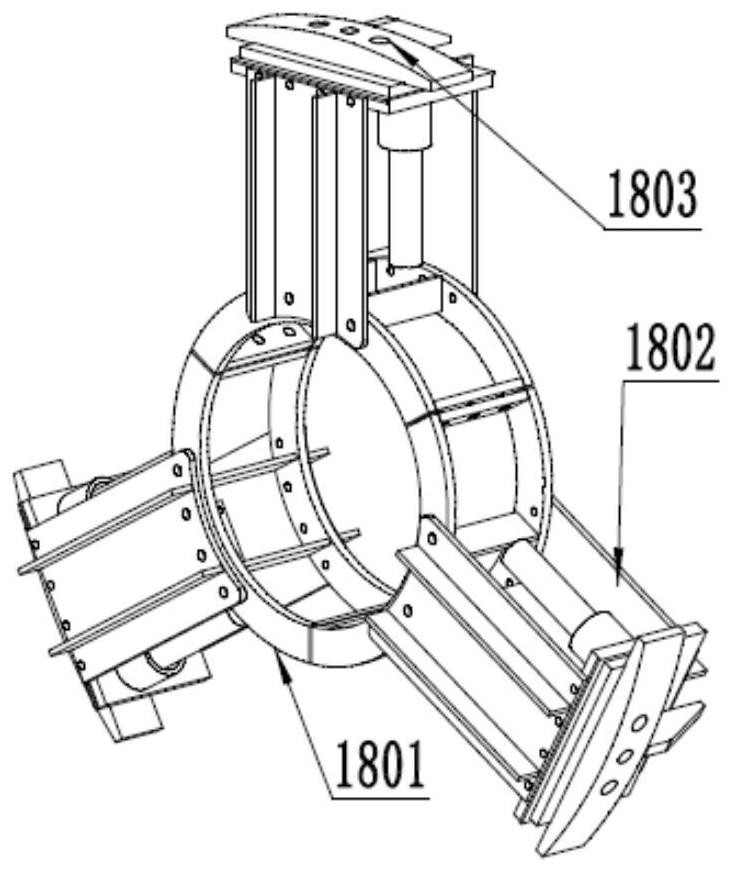
[0091] Such as Figure 1-10 As shown, in step S1, the inner ring fixing assembly includes a clamping hoop 1801 installed on the central shaft 1704, several connecting pieces 1802 fixedly connected with the clamping hoop 1801, and also includes a The connected supporting and fixing block 1803 slides along the connecting piece 1802 through the supporting hydraulic cylinder. In this embodiment, the number of connecting pieces 1802 is three, and each connecting piece 1802 is provided with a supporting and fixing block 1803, and the supporting and fixing block 1803 and the connecting piece 1802 adopt a guide shaft mechanism to realize sliding connection. Further, the connecting piece 1802 adopts It is composed of two flat plates parallel to each other, and the same end of the two plates is vertically fixedly connected with a flat plate to form a U-shaped structure. The supporting and fixing block 1803 is arranged on the U-shaped closed section, and the supporting hydraulic cylinder...

Embodiment 3

[0122] Such as Figure 1-15 As shown, in this embodiment, the base 1 is made of steel structure, the side of the base 1 is in the shape of "L", the roller mold assembly is located on the horizontal end of L, and the clamping assembly and the stopper 2 are respectively located on the roller mold assembly. Both ends; in this embodiment, the clamping assembly and the stopper 2 are installed on the roller mold assembly in a detachable manner, and the detachable method can be threaded connection, which is convenient for adjusting the position of the stopper 2 relative to the clamping assembly , can be applied to main bars of different specifications; the clamping component and the block 2 are equipped with parts for electrical conduction, when the main bar contacts with the stopper 2 and the clamping assembly at the same time, the length of the main bar can be detected by the electrical conduction And whether the main rib is in place.

[0123] The end stopper 201 is used to detect...


PUM


Abstract

The invention discloses a manufacturing method of a reinforcement cage. A winding reinforcement welding mechanism used for winding and welding winding reinforcements, a feeding mechanism used for feeding main reinforcements, a central rotating assembly used for rotating an inner ring, and an inner ring fixing assembly used for fixing the inner ring are included. A detection mechanism used for detecting the length of the main reinforcements and locating the main reinforcements, and a main reinforcement welding mechanism used for welding the main reinforcements are further included. According tothe manufacturing method, automatic machining is realized from feeding to welding and discharging of the reinforcement cage, welding spots of the reinforcement cage are stable, the welding quality ofthe reinforcement cage is stable, manpower input is reduced, the labor intensity of workers is relieved, the production efficiency of the reinforcement cage is greatly improved, and reinforcement cages of different specifications can be produced.

Description

technical field [0001] The invention relates to the field of reinforcement cage manufacture, in particular to a method for manufacturing a reinforcement cage. Background technique [0002] With the rapid development of domestic road and bridge construction, reinforcement cages are more and more widely used in pile foundation construction. Reinforcement cages mainly include three parts: main reinforcement, inner ring, and winding reinforcement. At present, most of the production methods of reinforcement cages are made by hand. The labor intensity of the workers is high, the production efficiency of the steel cage is low, and the labor cost is high; in this kind of production process, the welding alignment between the inner ring and the main reinforcement, and the welding of the winding reinforcement and the main reinforcement are all manually assisted and manual welding; In the mass production process, the labor intensity of the workers is high, therefore, the solder joints a...

Claims


Application Information

Patent Timeline
IPC IPC(8): B23K11/06B23K11/36
CPCB23K11/06B23K11/36
Inventor 徐小华向光明
Owner 成都华研机器设备有限公司
Why Eureka
Try Eureka