Adjustable machining limiting device

A limit device and machining technology, which is applied in positioning devices, metal processing equipment, metal processing machinery parts, etc., can solve the problems of poor flexibility of use and inability to adjust fixtures, etc., and achieve the effect of flexible use and stable limit

Inactive Publication Date: 2021-02-12
南京冉科信息技术有限公司
View PDF0 Cites 0 Cited by
  • Summary
  • Abstract
  • Description
  • Claims
  • Application Information

AI Technical Summary

Problems solved by technology

[0005] The object of the present invention is to provide a fixing device for mechanical processing that is convenient for position limitation, so as to solve the above-mentioned b

Method used


Image

  • Adjustable machining limiting device
  • Adjustable machining limiting device
  • Adjustable machining limiting device

Examples


Example Embodiment

[0019]The technical solutions in the embodiments of the present invention will be clearly and completely described below in conjunction with the drawings in the embodiments of the present invention.
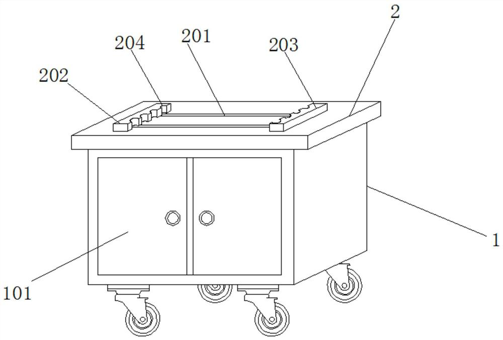
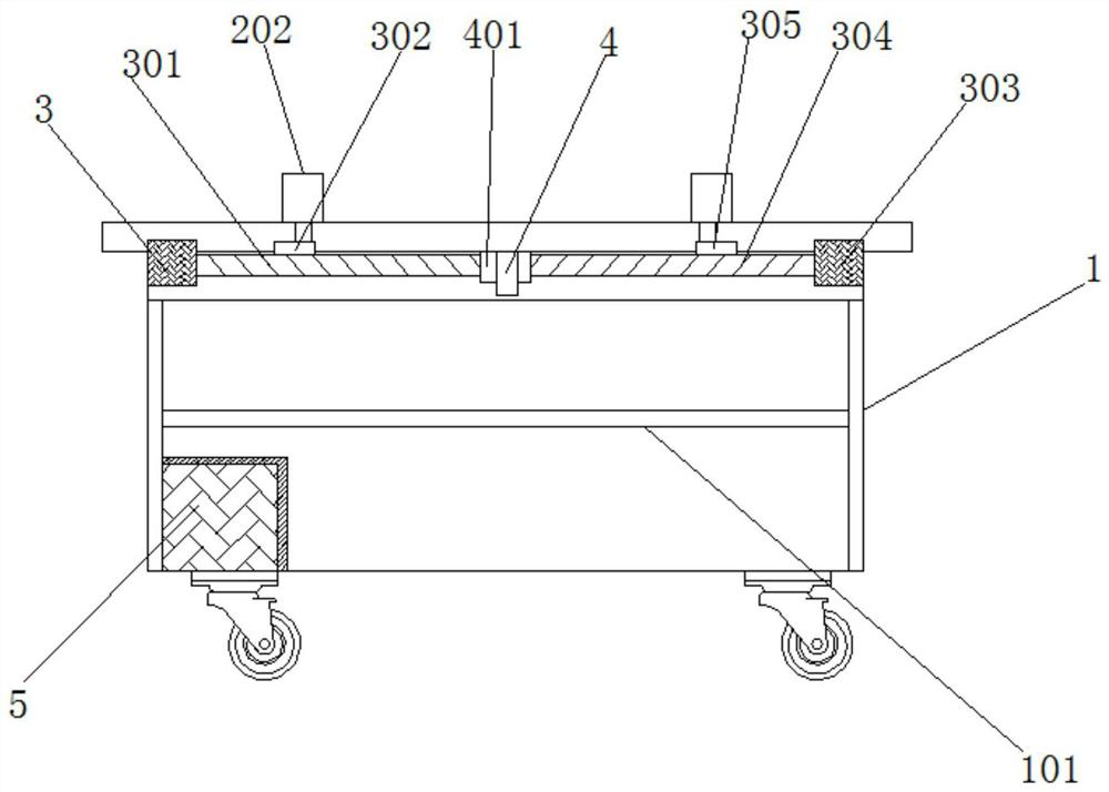
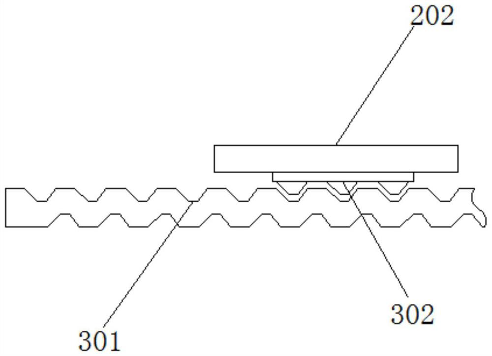
[0020]Such asFigure 1-3As shown, the present invention provides a technical solution: an adjustable machining limit device includes a cabinet body 1, a cabinet door 101, and a partition plate 102. A cabinet door 101 is movably installed on one side of the cabinet body 1 through a hinge. A partition plate 102 is fixedly installed in the inner cavity of the body 1, a workbench 2 is fixedly installed on the upper surface of the cabinet 1, and a sliding groove 201 is fixed on the upper surface of the workbench 2, and one end of the sliding groove 201 is movably installed with a number The clamp 202, the second end of the sliding groove 201 is movably installed with the No. 2 clamp 203, the inner wall surfaces of the No. 1 clamp 202 and the No. 2 clamp 203 are both provided with a limit card s...


PUM


Abstract

The invention discloses an adjustable machining limiting device. The adjustable machining limiting device comprises a cabinet body, a cabinet door and a partition plate, wherein the cabinet door is movably mounted on one side of the cabinet body through a hinge; the partition plate is fixedly mounted in an inner cavity of the cabinet body; a workbench is fixedly mounted on the upper surface of thecabinet body; a sliding groove is fixedly formed in the upper surface of the workbench; and a first clamp is movably mounted at one end of the sliding groove, and a second clamp is movably mounted atthe other end of the sliding groove. The diameters of limiting clamping grooves are sequentially increased, and therefore workpieces of different diameters can be clamped in the using process, and using is more flexible; worm and gear structures are matched to achieve the self-locking function, and therefore limiting of the workpieces can be more stable in the using process; and through mutual cooperation of a first motor and a second motor, the workpieces can be synchronously moved when limited, one set of clamps can be moved according to the using requirement, and using is more flexible.

Description

technical field [0001] The invention relates to the technical field of mechanical equipment, in particular to an adjustable machining limit device. Background technique [0002] The device used to fix the processing object in the process of mechanical manufacturing so that it occupies the correct position to accept construction or inspection, also known as fixture. In a broad sense, any process in the process, the device used to install the workpiece quickly, conveniently and safely, can be called a fixture. Such as welding fixtures, inspection fixtures, assembly fixtures, machine tool fixtures, etc. Among them, machine tool fixtures are the most common, often referred to as fixtures. When processing a workpiece on a machine tool, in order to make the surface of the workpiece meet the technical requirements such as the size, geometric shape, and mutual position accuracy with other surfaces specified in the drawing, the workpiece must be installed (positioned) and clamped (...

Claims


Application Information

Patent Timeline
IPC IPC(8): B23Q3/06B23Q1/25
CPCB23Q1/25B23Q3/06
Inventor 高磊
Owner 南京冉科信息技术有限公司
Why Eureka
Try Eureka