Posture smooth transition method and system
A technology of smooth transition and attitude, applied in the field of robotics, can solve the problem that the time derivative of the transition curve has no clear meaning.
- Summary
- Abstract
- Description
- Claims
- Application Information
AI Technical Summary
Problems solved by technology
Method used
Image
Examples
Embodiment 1
[0085] This embodiment provides a detailed description of the gesture smooth transition method.
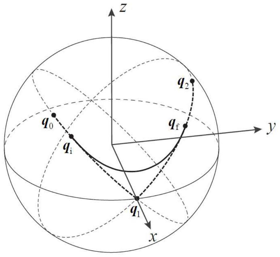
[0086] A method for attitude smooth transition, three attitudes q are known 0 ,q 1 ,q 2 , where by the pose q 0 to q 1 The axis of rotation is u 0 , the rotation angle is α 0 >0; by q 1 to q 2 The axis of rotation is u 1 , the rotation angle is α 1 >0; u 0 and u 1 The included angle is β, β≠0.
[0087] Select a reference coordinate system, and the coordinate vectors i, j, k of the reference system are determined by the following formula:
[0088]
[0089] In the reference frame, the axis of rotation u 0 , u 1 Expressed as
[0090]
[0091] The attitude is represented by the unit quaternion, according to the spherical linear interpolation, by q 0 to q 1 The interpolation curve of can be expressed by the following parametric equation:
[0092] q 01 (s)=p 01 (s)q 1 , s ∈ [0, 1]
[0093] s is a parameter and
[0094]
[0095] represented by pose q 1 to...
Embodiment 2
[0173] This embodiment provides when α 0 = 120°, α 1 =150°, α=90°, β=90°, q 0 = (1, (0, 0, 0)), the detailed description of the attitude transition curve is determined.
[0174] According to α and β, according to formula (4) to obtain
[0175]
[0176] θ m =arcsin(sin45°cos45°)=30°
[0177] By formula (6) get
[0178]
[0179] By formula (9) get
[0180]
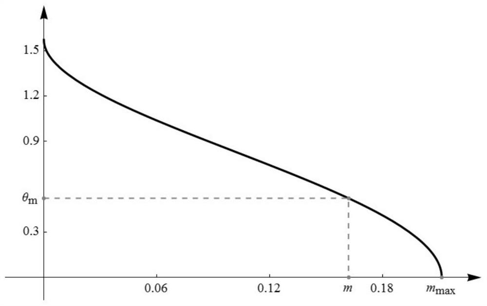
[0181] Using dichotomy, in the interval [0, m max ] to search for the root of m in formula (8), and get
[0182] m=0.161838
[0183] figure 1 For the right side of formula (8) in the interval [0, m max ] on the change graph, the vertical coordinate in the graph is θ m The abscissa value corresponding to the point is equal to m.
[0184] Calculated according to formula (6), formula (7) and formula (10)
[0185] n=0.265482, c ψ = 1.268094, σ = 2.587944
[0186] put m,n,c ψ , η, θ m Substituting the value of in turn into formula (5) and formula (3), we can get p 0 (s), p 1 (s) and p 2 The detailed e...
Embodiment 3
[0195] This embodiment provides an explanation of trajectory planning for the attitude transition curve in Embodiment 2 according to the change law of angular velocity.
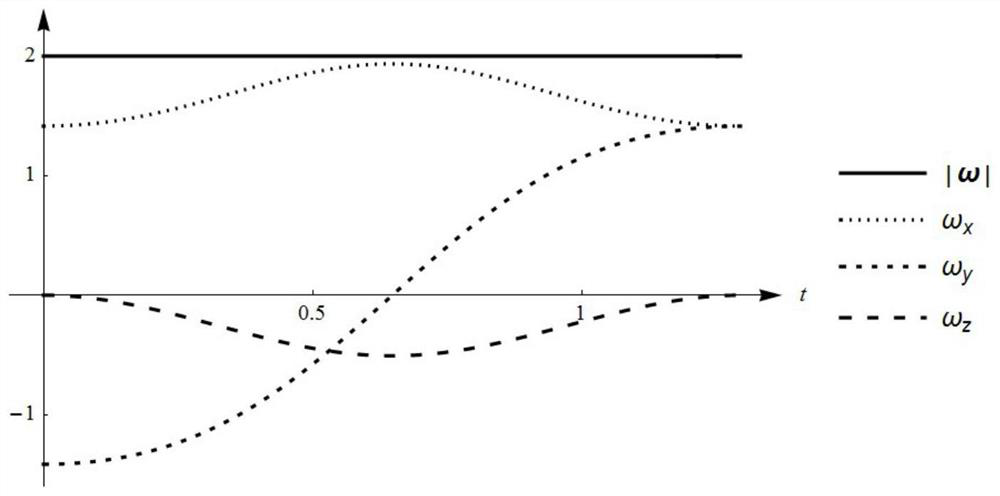
[0196] The attitude transition curve that obtains in embodiment 2 is carried out trajectory planning, promptly determines the variation law s (t) of the parameter s in the transition curve parametric equation about time. The change law of known angular velocity is: at the starting point q i and endpoint q f The magnitude of the angular velocity is 2, and by q i transition to q f The angular velocity is kept constant during the process.
[0197] Using the derivative of parameter s with respect to time is equal to the magnitude of angular velocity, we can get the change law of parameter s with respect to time, s(t) should be:
[0198] s(t)=2t, t∈[0,σ / 2]
[0199] After both q(s) and s(t) are determined, the change law of attitude over time can be obtained, image 3 It is the magnitude of the angular veloci...
PUM
 Abstract
Description
Claims
Application Information
 - R&D
- Intellectual Property
- Life Sciences
- Materials
- Tech Scout
- Unparalleled Data Quality
- Higher Quality Content
- 60% Fewer Hallucinations
Browse by: Latest US Patents, China's latest patents, Technical Efficacy Thesaurus, Application Domain, Technology Topic, Popular Technical Reports.
© 2025 PatSnap. All rights reserved.Legal|Privacy policy|Modern Slavery Act Transparency Statement|Sitemap|About US| Contact US: help@patsnap.com


