Method and system for smooth transition of attitude

A technology of smooth transition and attitude, applied in the field of robotics, can solve the problem that the time derivative of the transition curve has no clear meaning, and achieve the effect of facilitating trajectory planning

Active Publication Date: 2022-05-03
HRG INT INST FOR RES & INNOVATION
View PDF6 Cites 0 Cited by
  • Summary
  • Abstract
  • Description
  • Claims
  • Application Information

AI Technical Summary

Problems solved by technology

This invention application uses B-splines with 5 control points to construct the attitude transition curve. The constructed attitude transition curve and the front and rear attitude interpolation curves have two-order geometric continuity at the junction, but the parameters of the transition curve have no clear meaning to the time derivative. , it is difficult to plan the trajectory according to the changing law of angular velocity

Method used


Image

  • Method and system for smooth transition of attitude
  • Method and system for smooth transition of attitude
  • Method and system for smooth transition of attitude

Examples


Embodiment 1

[0085] This embodiment provides a detailed description of the gesture smooth transition method.

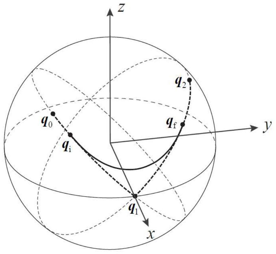
[0086] A method for attitude smooth transition, three attitudes q are known 0 ,q 1 ,q 2 , where by the pose q 0 to q 1 The axis of rotation is u 0 , the rotation angle is α 0 >0; by q 1 to q 2 The axis of rotation is u 1 , the rotation angle is α 1 >0; u 0 and u 1 The included angle is β, β≠0.

[0087] Select a reference coordinate system, and the coordinate vectors i, j, k of the reference system are determined by the following formula:

[0088]

[0089] In the reference frame, the axis of rotation u 0 , u 1 Expressed as

[0090]

[0091] The attitude is represented by the unit quaternion, according to the spherical linear interpolation, by q 0 to q 1 The interpolation curve of can be expressed by the following parametric equation:

[0092] q 01 (s)=p 01 (s)q 1 , s ∈ [0, α 0 ]

[0093] s is a parameter and

[0094]

[0095] represented by pose q ...

Embodiment 2

[0173] This embodiment provides when α 0 = 120°, α 1 =150°, α=90°, β=90°, q 1 = (1, (0, 0, 0)), the detailed description of the attitude transition curve is determined.

[0174] According to α and β, according to formula (4) to obtain

[0175]

[0176] θ m =arcsin(sin45°cos45°)=30°

[0177] By formula (6) get

[0178]

[0179] By formula (9) get

[0180]

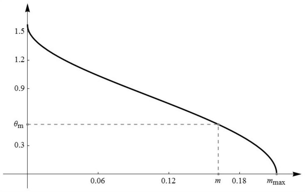
[0181] Using dichotomy, in the interval [0, m max ] to search for the root of m in formula (8), and get

[0182] m=0.161838

[0183] figure 1 For the right side of formula (8) in the interval [0, m max ] on the change graph, the vertical coordinate in the graph is θ m The abscissa value corresponding to the point is equal to m.

[0184] Calculated according to formula (6), formula (7) and formula (10)

[0185] n=0.265482, c ψ = 1.268094, σ = 2.587944

[0186] put m,n,c ψ , η, θ m Substituting the value of in turn into formula (5) and formula (3), we can get p 0 (s), p 1 (s) and p 2 The detailed e...

Embodiment 3

[0197] This embodiment provides an explanation of trajectory planning for the attitude transition curve in Embodiment 2 according to the change law of angular velocity.

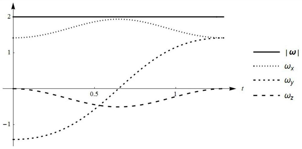
[0198] Perform trajectory planning on the attitude transition curve obtained in Embodiment 2, that is, determine the change law s(t) of the parameter s in the transition curve parameter equation with respect to time. The change law of known angular velocity is: at the starting point q i and endpoint q f The magnitude of the angular velocity is 2, and by q i transition to q f The angular velocity is kept constant during the process.

[0199] Using the derivative of parameter s with respect to time is equal to the size of angular velocity, we can get the variation law of parameter s with respect to time, s(t) should be

[0200] s(t)=2t, t∈[0,σ / 2]

[0201] After both q(s) and s(t) are determined, the change law of attitude over time can be obtained, image 3 It is the magnitude of the angular velocity ω an...


PUM


Abstract

The present invention proposes a smooth attitude transition method, the constructed attitude transition curve and the front and rear attitude interpolation curves have two-order geometric continuity at the junction, which can realize smooth angular velocity everywhere and continuous angular acceleration everywhere; in addition, the parameters in the transition curve parameter equation The time derivative is equal to the magnitude of the angular velocity, which is convenient for trajectory planning according to the change rule of the angular velocity.

Description

technical field [0001] The invention relates to the technical field of robots, in particular to a method and system for smooth transition of postures. Background technique [0002] The robot programming system provides several basic motion commands, such as linear motion, circular motion, etc. The robot executes motion instructions one by one, and the tool center point moves along the path defined by the instructions. If it is not set, the speed of the robot at the target point of each instruction is zero. For some applications, in order to improve efficiency, it is hoped that the robot can keep moving between adjacent instructions, and the robot is allowed to deviate from the path within a certain range. A typical solution to this problem is to insert a transition path between the paths defined by adjacent instructions. In order to ensure smooth movement and avoid impacts on the machine body caused by acceleration jumps, the transition path and the front and rear path se...

Claims


Application Information

Patent Timeline
Patent Type & Authority Patents(China)
IPC IPC(8): B25J9/16G06F17/15
CPCB25J9/1664G06F17/15
Inventor 王华郭庆洪吴自翔于振中李文兴
Owner HRG INT INST FOR RES & INNOVATION
Why Eureka
Try Eureka