Novel multifunctional carrying trolley
A kind of handling trolley, multi-functional technology, applied in the field of new multi-functional handling trolley, can solve the problems of complicated site conditions, cumbersome steps, inconvenient, etc., and achieve the effect of saving labor
- Summary
- Abstract
- Description
- Claims
- Application Information
AI Technical Summary
Problems solved by technology
Method used
Image
Examples
Embodiment 1
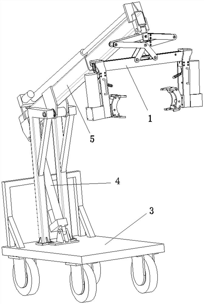
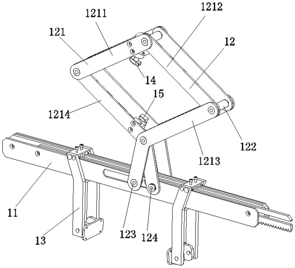
[0040] Embodiment one: if figure 2 As shown, the automatic clamping device 1 includes: a rack set 11, a lever plate 12 whose lower end is movably assembled on the rack set 11, and two lever plates 12 whose upper end is movably assembled on the rack set 11 and located on the left and right sides of the lever plate 12. Clamp feet 13 are assembled on the self-locking swivel 14 on the upper side of the lever plate 12 , and are assembled on the base 15 on the lower side of the lever plate 12 . The rotation positioning group 2 is located inside the pin 13; the expansion and contraction of the lever plate 12 drives the rack group 11 to slide and then drives the pin 13 to slide; the self-locking rotary sleeve 14 presses down or lifts and rotates by 45°.
[0041] Specifically: in the initial state, self-locking between the self-locking rotary sleeve 14 and the base 15, and then the lever plate 12 is locked, and then the clamping feet 13 are locked and fixed; when the automatic clampin...
Embodiment 2
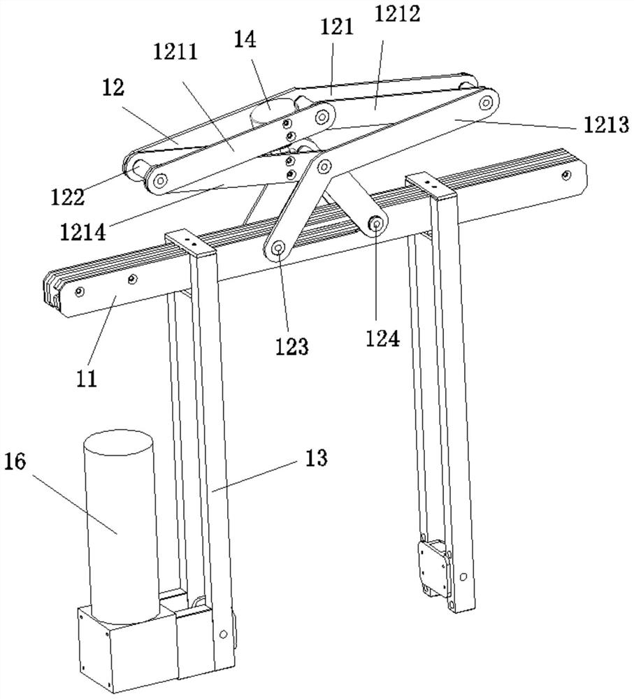
[0048] Embodiment two: on the basis of embodiment one, as image 3 As shown, the automatic clamping device 1 further includes: a rotating motor 16 whose output end is connected to the lower outer end of the clamping foot 13 and used to drive the automatic clamping device 1 to turn over. By providing the rotating motor 16, it can drive the automatic clamping device 1 to turn over, and then drive the object to turn over, which can greatly save labor in some specific occasions.
Embodiment 3
[0049] Embodiment three: on the basis of embodiment one or embodiment two, as Figure 4 As shown, the automatic clamping device 1 further includes: two rotating positioning groups 2 respectively provided at the lower inner ends of the clamping feet 13 for clamping objects. The rotation positioning group 2 includes: a left meniscus 21 and a right meniscus 22 arranged symmetrically, and an upper connection plate 23 fixedly connected to the upper side between the left meniscus 21 and the right meniscus 22, and fixedly connected to the left meniscus 21 and the right meniscus. The lower connecting plate 24 on the lower side between the menisci 22 is rotatably assembled on the upper meniscus 25 on the upper side of the upper connecting plate 23 , and the lower meniscus 26 on the lower side of the lower connecting plate 24 is rotatably assembled. By providing the rotation positioning group 2, and the rotation positioning group 2 includes four menisci, when the meniscus of the rotatio...
PUM
 Abstract
Description
Claims
Application Information
 - R&D
- Intellectual Property
- Life Sciences
- Materials
- Tech Scout
- Unparalleled Data Quality
- Higher Quality Content
- 60% Fewer Hallucinations
Browse by: Latest US Patents, China's latest patents, Technical Efficacy Thesaurus, Application Domain, Technology Topic, Popular Technical Reports.
© 2025 PatSnap. All rights reserved.Legal|Privacy policy|Modern Slavery Act Transparency Statement|Sitemap|About US| Contact US: help@patsnap.com


