
A liquid beverage filling valve

A valve and beverage technology, used in liquid bottling, liquid processing, fluid distribution valves, etc., can solve problems such as position offset, liquid outflow, inability to control liquid speed, etc., and achieve the effect of uniform flow rate and stable flow rate.

Active Publication Date: 2022-05-31
德清三盛氟塑科技有限公司
View PDF8 Cites 0 Cited by
  • Summary
  • Abstract
  • Description
  • Claims
  • Application Information

AI Technical Summary

Problems solved by technology

[0003] The object of the present invention is to provide a liquid beverage filling valve, which solves the problem that the existing filling valve cannot control the speed of the liquid in the filling process, and can not buffer the flow rate of the filling liquid and Uniform, secondly, the existing bottle body and the bottom of the filling valve cannot be connected stably, and the position is shifted, which will cause the problem of liquid outflow during filling

Method used


Image

  • A liquid beverage filling valve
  • A liquid beverage filling valve
  • A liquid beverage filling valve

Examples


Embodiment Construction

[0025] Examples of the described embodiments are illustrated in the accompanying drawings, wherein the same or similar reference numbers represent the same or similar throughout

[0026] In the present invention, unless otherwise expressly specified and limited, the terms "installed", "connected", "connected", "fixed", etc.

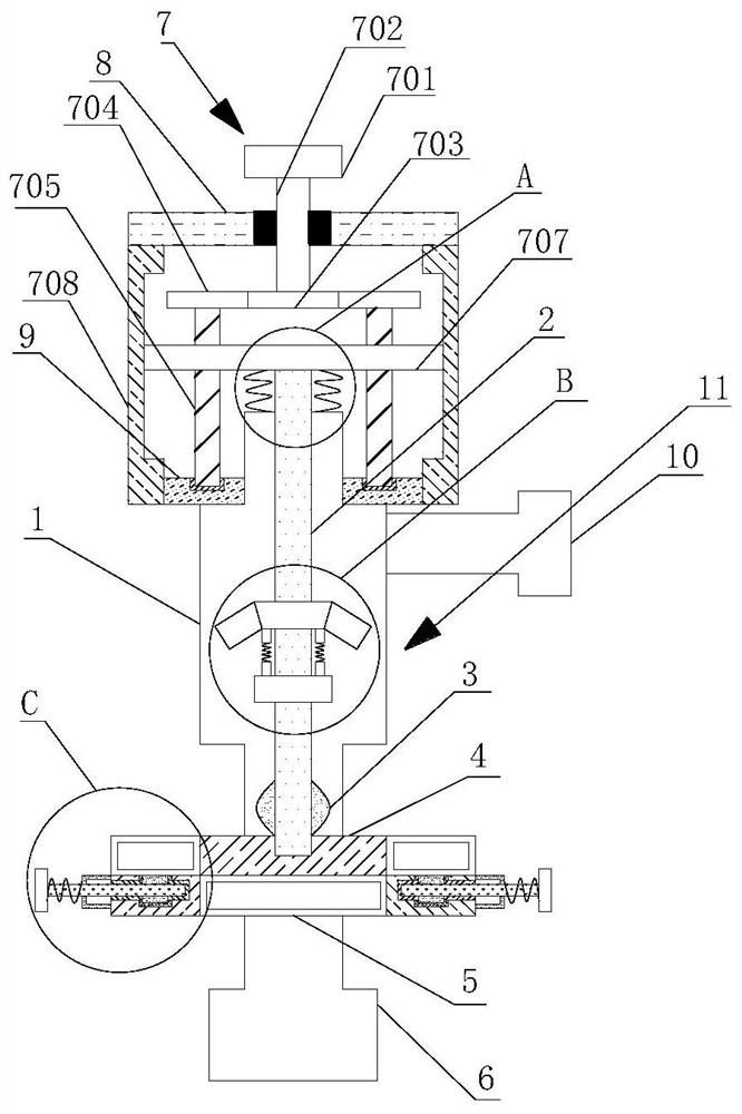
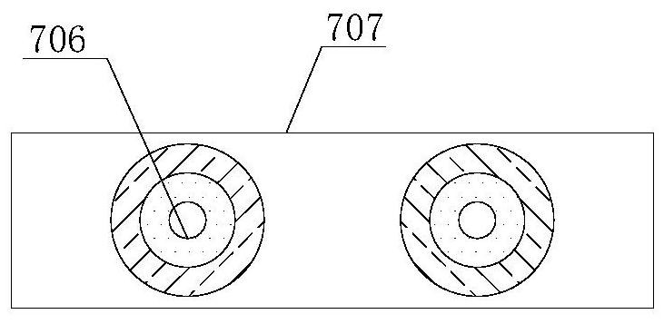
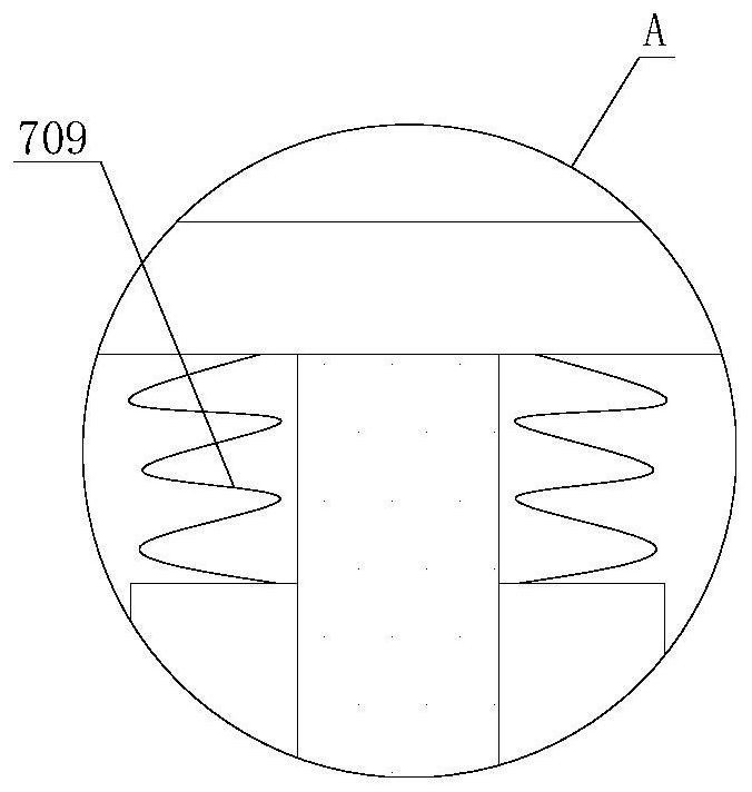
[0029] The adjustment mechanism 7 includes a knob 701, a connecting shaft 702, a first gear 703, a second gear 704, a threaded rod 705, a thread

[0033] Although embodiments of the present invention have been shown and described, it will be apparent to those of ordinary skill in the art that


PUM


Abstract

The invention relates to the technical field of filling equipment, and discloses a liquid beverage filling valve, which includes a valve body, an adjustment mechanism, and a diversion buffer mechanism. On the outer wall of the lower end, the top of the air return pipe extends through the top of the inner wall of the valve to the top of the valve body; . The second collar, the first collar is sleeved on the outer wall of the air return pipe. In the liquid beverage filling valve, the connecting shaft can drive the first gear to rotate by rotating the knob, so that the second gear can be rotated, and the threaded rod can be rotated by the rotation of the second gear, and the threaded sleeve can drive the moving rod to move downward. Indirectly, the air return pipe can drive the valve sleeve to move downwards, and finally the size of the gap between the valve sleeve and the opening in the middle of the adjustment pad can be controlled, and the flow rate can be controlled.

Description

A liquid beverage filling valve technical field [0001] The present invention relates to the technical field of filling equipment, in particular to a liquid beverage filling valve. Background technique With the development of the beverage industry, the filling machinery develops rapidly, the filling bottles are various, and the volume is also different in size. During the filling process of some large-volume bottles, a higher filling speed is required to meet the requirements of filling liquid. During the filling process, the valve mouth corresponds to the bottle mouth of the bottle body, and the filling is realized after the bottle body and the filling barrel are connected. Existing filling valve The velocity of the liquid in the filling cannot be controlled during the filling process, and the flow rate of the filling liquid cannot be buffered and Evenly, secondly, the existing bottle body and the bottom of the filling valve cannot be stably connected, and the posit...

Claims


Application Information

Patent Timeline
Patent Type & Authority Patents(China)
IPC IPC(8): B67C3/28F16K21/00F16K47/02
CPCB67C3/28F16K21/00F16K47/02
Inventor 徐建华
Owner 德清三盛氟塑科技有限公司
Learn More