Rotational flow air inlet centrifugal draught fan

A centrifugal fan and blower technology, applied in mechanical equipment, radial flow pumps, machines/engines, etc., can solve the problem that the swirling air inlet centrifugal fan cannot absorb air, affect the normal operation of the swirling air inlet centrifugal fan, and the deformation of the impeller, etc. question

Active Publication Date: 2021-02-12
重庆沃亚机械有限公司
View PDF6 Cites 1 Cited by
  • Summary
  • Abstract
  • Description
  • Claims
  • Application Information

AI Technical Summary

Problems solved by technology

[0004] Aiming at the problems in the prior art, the present invention provides a swirl inlet centrifugal fan, which solves the problem that most of the impellers of the swirl inlet centrifugal fan are exposed to the outside when the swirl inlet centrifugal fan currently used is sucking air. During the transportation process, if it is subjected to external impact and the force acts on the impeller, it is easy to cause the impeller to be deformed and damaged, making the swirl inlet centrifugal fan unable to suck air. When the swirl inlet centrifugal fan is squeezed by a large object The casing of the swirl inlet centrifugal fan is prone to deformation. If there are large foreign objects floating in the air around the swirl inlet centrifugal fan, such as leaves, these foreign objects will be sucked into the swirl inlet centrifugal fan. The inside of the fan is easy to be blocked in the swirl inlet centrifugal fan, which affects the normal operation of the swirl inlet centrifugal fan

Method used


Image

  • Rotational flow air inlet centrifugal draught fan
  • Rotational flow air inlet centrifugal draught fan
  • Rotational flow air inlet centrifugal draught fan

Examples


Embodiment Construction

[0029] In order to make the technical means, creative features, goals and effects achieved by the present invention easy to understand, the present invention will be further described below in conjunction with specific embodiments.

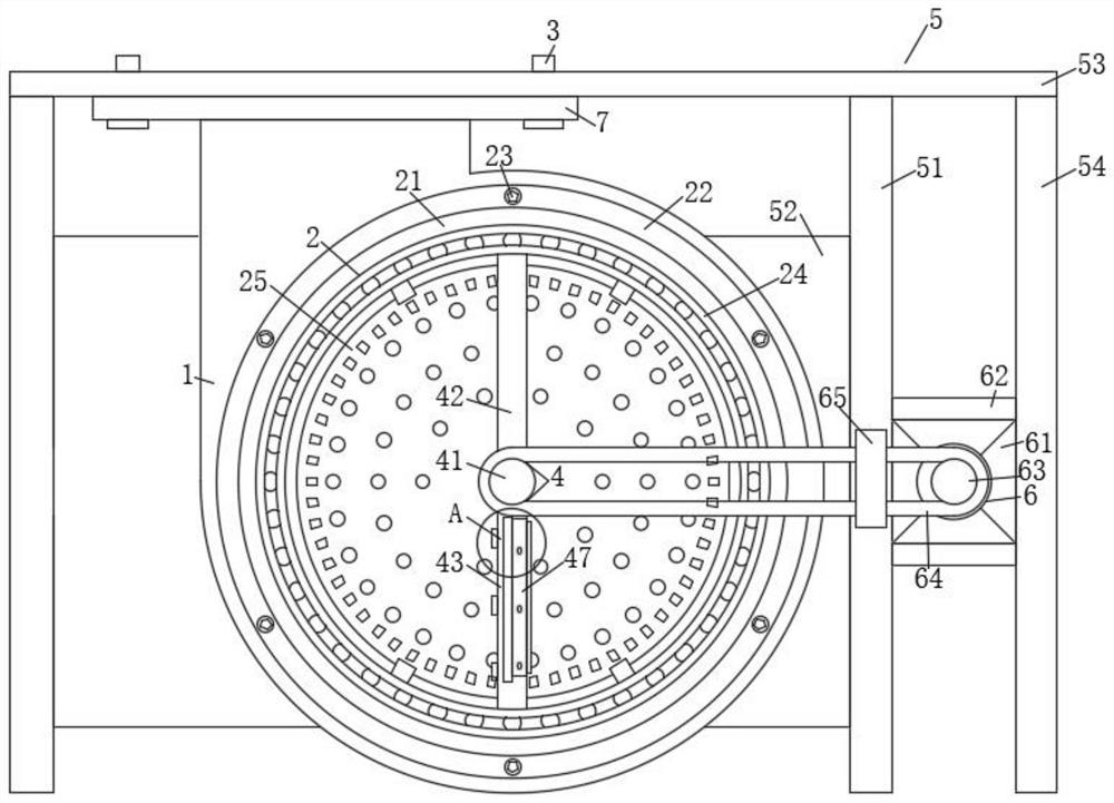
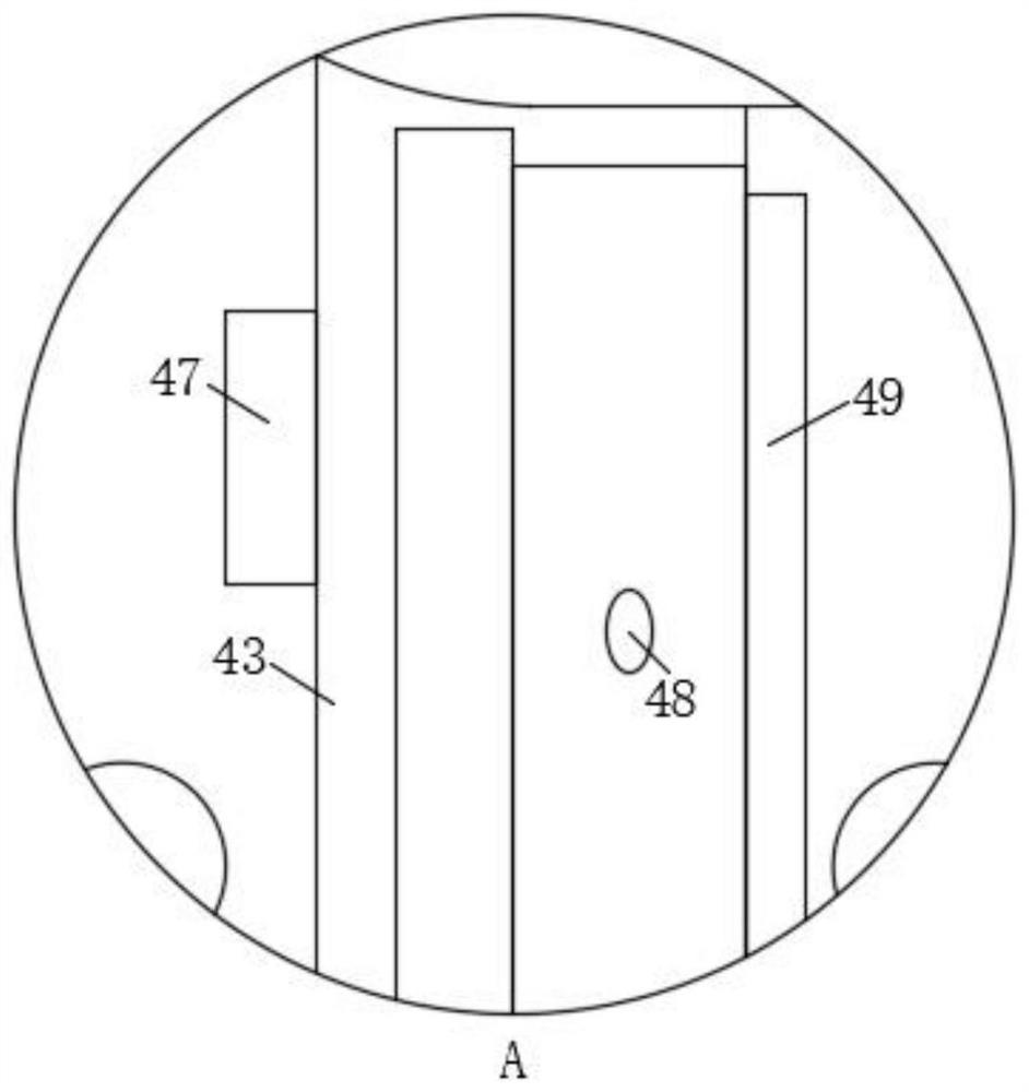
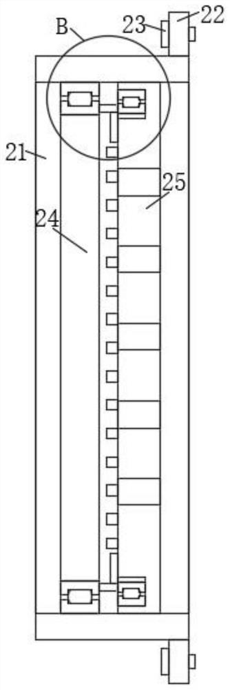
[0030] Such as Figure 1-Figure 9 As shown, a swirling air inlet centrifugal fan according to the present invention includes a fan main body 1, a protective mechanism 2 is installed on the front outer wall of the fan main body 1, and the protective mechanism 2 is located on the front of the impeller of the fan main body 1, The protection mechanism 2 is connected with a cleaning mechanism 4, the air outlet of the main body of the fan 1 faces upwards and is fixedly connected with a mounting ring 7 at the air outlet, and a fixed frame 5 is installed on the side outer wall of the main body of the fan 1, and the fixed frame 5 is equipped with a driving mechanism 6, the driving mechanism 6 is connected with the cleaning mechanism 4, and the driving mech...


PUM


Abstract

The invention relates to the field of air purification, in particular to a rotational flow air inlet centrifugal draught fan. The draught fan comprises a draught fan body; a protection mechanism is installed on the outer wall of the front face of the draught fan body and located on the front face of an impeller of the draught fan body; the protection mechanism is connected with a cleaning mechanism; an air outlet of the draught fan body faces upwards, and an installation ring is fixedly connected with the air outlet; a fixing frame is installed on the outer wall of the side face of the draughtfan body; a driving mechanism is installed on the fixing frame; and the driving mechanism is connected with the cleaning mechanism. According to the rotational flow air inlet centrifugal draught fan,the protection mechanism is installed on the front face of the impeller of the draught fan body, a net plate of the protection mechanism is arranged on the front face of the impeller of the draught fan body, the impeller is sealed in the draught fan body, and when the draught fan is impacted by external acting force, the net plate can prevent the acting force from directly acting on the impeller,damaging the impeller and weakening the air suction capacity of the draught fan.

Description

technical field [0001] The invention relates to the field of air purification, in particular to a swirling air inlet centrifugal fan. Background technique [0002] The swirling air inlet centrifugal fan is a kind of centrifugal fan. When purifying the air, the swirling air inlet centrifugal fan is used to suck the air to be purified into the purification equipment for purification. [0003] Most of the impellers of the currently used swirl inlet centrifugal fans are exposed to the outside when they are sucking air. The damage makes the swirl inlet centrifugal fan unable to suck air. When the larger object of the swirl inlet centrifugal fan is squeezed, the casing of the swirl inlet centrifugal fan is prone to deformation. If the air around the swirl inlet centrifugal fan There are large foreign objects floating in the air, such as leaves and other foreign objects, these foreign objects will be sucked into the inside of the swirl inlet centrifugal fan, and they are easy to b...

Claims


Application Information

Patent Timeline
IPC IPC(8): F04D25/08F04D17/16F04D29/70F04D29/00F04D29/62
CPCF04D25/08F04D17/16F04D29/703F04D29/002F04D29/626
Inventor 鲍岚臧龙
Owner 重庆沃亚机械有限公司
Why Eureka
Try Eureka