Heat supply equipment convenient for mounting electromagnetic flowmeter

An electromagnetic flowmeter, a convenient technology, applied in the application of electromagnetic flowmeters to detect fluid flow, volume/mass flow generated by electromagnetic effects, and measuring devices, etc., can solve the inconvenience of installation and disassembly, increase the difficulty of work, and inconvenience the normal passage of pipelines, etc. question

Pending Publication Date: 2021-02-12
湖南达道新能源开发有限公司
View PDF10 Cites 1 Cited by
  • Summary
  • Abstract
  • Description
  • Claims
  • Application Information

AI Technical Summary

Problems solved by technology

Electromagnetic flowmeter is an instrument that uses the principle of electromagnetic induction to measure the flow rate of conductive fluid according to the electromotive force induced when the conductive fluid passes through an external magnetic field. At present, electromagnetic flowmeters are generally installed and fixed by several sets of bolts and nuts when installed. This method Due to the narrow connection at both ends of the electromagnetic flowmeter during installation, it is inconvenient to operate with a wrench when fixing with bolts and nuts, resulting in inconvenient installation and disassembly work, which increases the difficulty of work and reduces work efficiency. After measuring, it is easy to affect the normal operation of the pipeline, and it is inconvenient for the normal passage of the pipeline. However, the electromagnetic flowmeter is installed between the pipelines.

Method used


Image

  • Heat supply equipment convenient for mounting electromagnetic flowmeter
  • Heat supply equipment convenient for mounting electromagnetic flowmeter
  • Heat supply equipment convenient for mounting electromagnetic flowmeter

Examples


Embodiment Construction

[0019] The present invention will be further described below in conjunction with the accompanying drawings and embodiments.

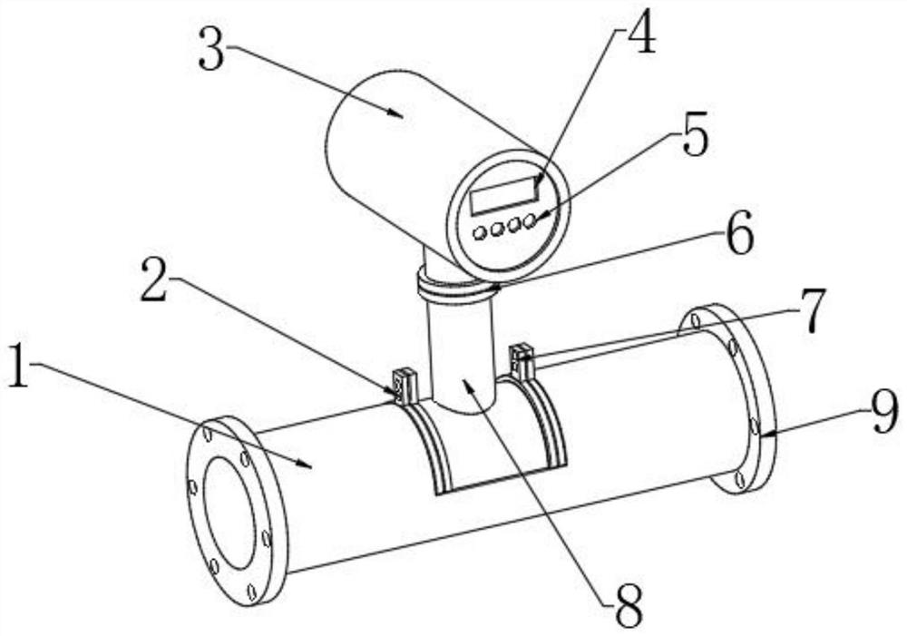
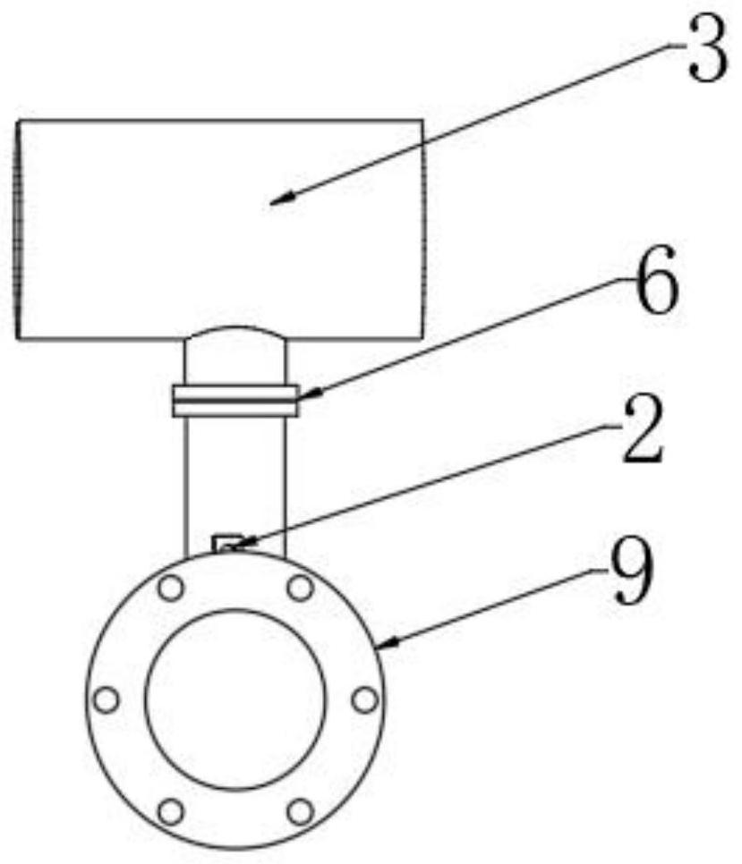
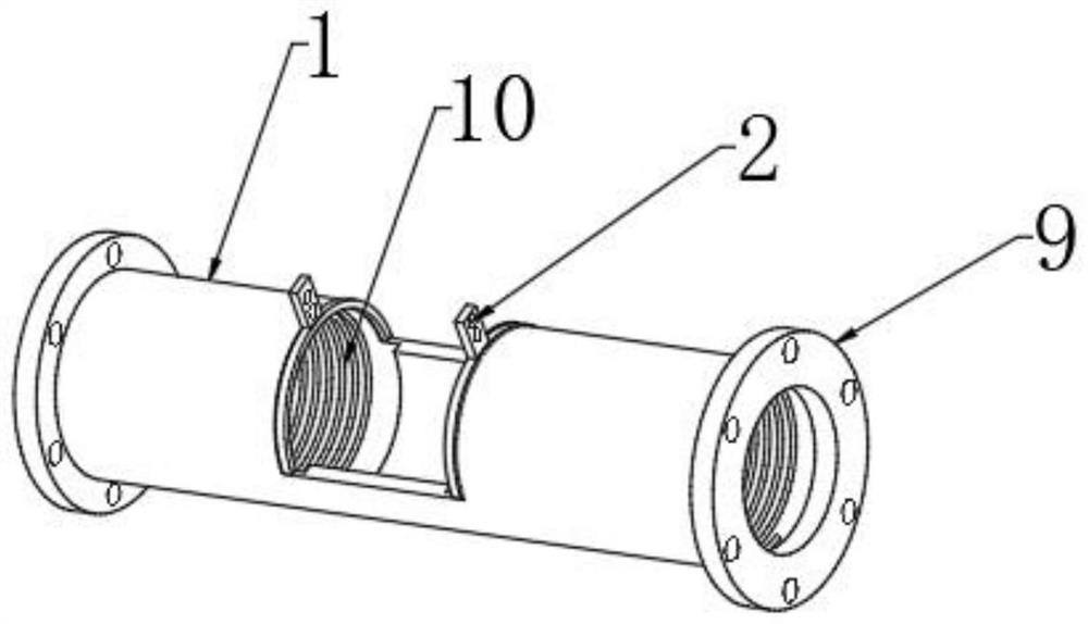
[0020] Please refer to figure 1 , figure 2 and image 3 ,in, figure 1 It is a schematic diagram of a three-dimensional structure of a preferred embodiment of the present invention; figure 2 for figure 1 The schematic diagram of the structure shown in the side plane; image 3 for figure 1 A schematic diagram of the internal structure is shown. In the specific implementation process, such as figure 1 and figure 2 As shown, it includes: a pipeline 1, a flange ring 9 is spirally installed at both ends of the pipeline 1, a spring 10 is sleeved inside the flange ring 9, and a collar 11 is installed at the other end of the spring 10. The top of the collar 11 is welded with a first fixing buckle 2, and the first fixing buckle 2 is fixedly installed with an electromagnetic flowmeter 3, and the electromagnetic flowmeter 3 is provided with a display 4,...


PUM


Abstract

The invention provides heat supply equipment convenient for mounting an electromagnetic flowmeter. The heat supply equipment comprises a pipeline, flange rings are spirally mounted at two ends of thepipeline, springs are mounted in the flange rings in a sleeving manner, lantern rings are mounted at the other ends of the springs, first fixing buckles are welded at the top ends of the lantern rings, the electromagnetic flowmeter is fixedly installed on the first fixing buckles and provided with a display, an adjusting button is arranged at the bottom end of the display, a fixing ring is weldedto the bottom end of the electromagnetic flowmeter, a supporting column is connected with the bottom end of the fixing ring, second fixing buckles are welded to the two sides of the supporting column,the first fixing buckles and the second fixing buckles are the same in size and provided with fixing holes, and the number of the fixing holes formed in the first fixing buckles and the number of thefixing holes formed in the second fixing buckles are two. The heat supply equipment has the advantages that the structure is simple, mounting and dismounting are convenient, normal operation of the pipeline is not affected after the electromagnetic flowmeter is dismounted, and practicability is high.

Description

technical field [0001] The invention relates to the technical field of electromagnetic flowmeter installation, in particular to heat supply equipment for convenient installation of electromagnetic flowmeters. Background technique [0002] Electromagnetic flowmeter is a new type of flow measuring instrument developed rapidly with the development of electronic technology in the 1950s and 1960s. Electromagnetic flowmeter is an instrument that uses the principle of electromagnetic induction to measure the flow rate of conductive fluid according to the electromotive force induced when the conductive fluid passes through an external magnetic field. At present, electromagnetic flowmeters are generally installed and fixed by several sets of bolts and nuts when installed. This method Due to the narrow connection at both ends of the electromagnetic flowmeter during installation, it is inconvenient to operate with a wrench when fixing with bolts and nuts, resulting in inconvenient inst...

Claims


Application Information

Patent Timeline
Patent Type & Authority Applications(China)
IPC IPC(8): G01F1/58G01F15/18
CPCG01F1/58G01F15/18
Inventor 刘艺辉李进
Owner 湖南达道新能源开发有限公司
Why Eureka
Try Eureka