Electronic device acceleration bearing force experiment equipment
A technology of electronic devices and experimental equipment, applied in the direction of instruments, measuring electricity, measuring electrical variables, etc., can solve the problems of few types of components, the inability to fix electronic components of different shapes and sizes, and affect the normal use of components, etc., to achieve The effect of reducing vibration, avoiding detection problems, and reducing difficulty of observation
- Summary
- Abstract
- Description
- Claims
- Application Information
AI Technical Summary
Problems solved by technology
Method used
Image
Examples
Embodiment 1
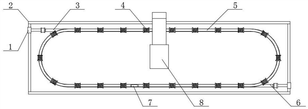
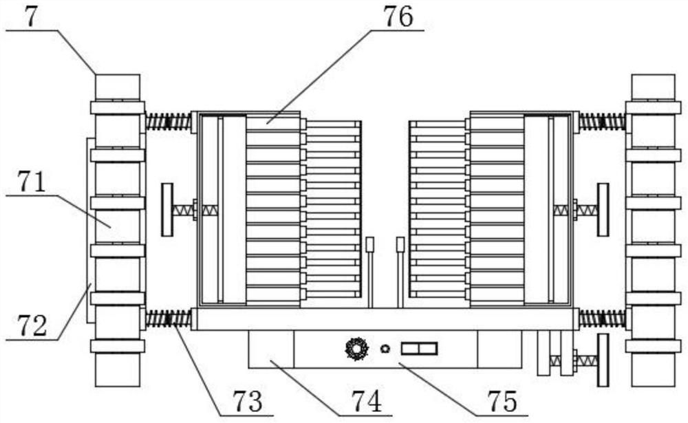
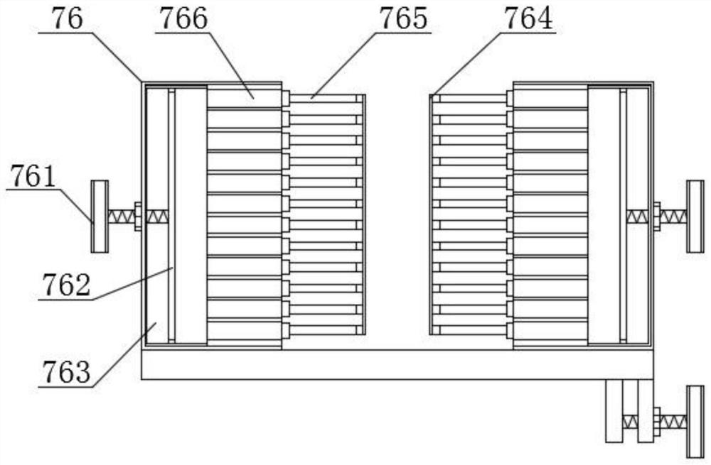
[0031] Such as Figure 1-4 As shown, the electronic device acceleration bearing test equipment includes a base plate 2, a monitoring camera 8 is fixed on the upper end of the base plate 2, a glass tube 5 is fixed on the front end of the base plate 2, and an accelerating electromagnet 4 and a glass tube 5 are fixed on the surface of the glass tube 5. The left end of the glass tube 5 is fixed with an inlet tube 3, the right end of the glass tube 5 is fixed with a detachment tube 6, the surface of the inlet tube 3 and the detachment tube 6 is sleeved with a blocking device 1, and the inner surface of the glass tube 5 is slidingly connected with a test device 7, the test device 7 includes a fixing device 76, the lower end of the fixing device 76 is fixed with a counterweight 74, the middle of the counterweight 74 is fixed with a detection device 75 at the lower end of the fixing device 76, and the left and right ends of the fixing device 76 are fixed with a twisting device 73 , th...
Embodiment 2
[0034] Such as Figure 1-5 As shown, the electronic device acceleration bearing test equipment includes a base plate 2, a monitoring camera 8 is fixed on the upper end of the base plate 2, a glass tube 5 is fixed on the front end of the base plate 2, and an accelerating electromagnet 4 and a glass tube 5 are fixed on the surface of the glass tube 5. The left end of the glass tube 5 is fixed with an inlet tube 3, the right end of the glass tube 5 is fixed with a detachment tube 6, the surface of the inlet tube 3 and the detachment tube 6 is sleeved with a blocking device 1, and the inner surface of the glass tube 5 is slidingly connected with a test device 7, the test device 7 includes a fixing device 76, the lower end of the fixing device 76 is fixed with a counterweight 74, the middle of the counterweight 74 is fixed with a detection device 75 at the lower end of the fixing device 76, and the left and right ends of the fixing device 76 are fixed with a twisting device 73 , th...
Embodiment 3
[0037] Such as Figure 1-8 As shown, the electronic device acceleration bearing test equipment includes a base plate 2, a monitoring camera 8 is fixed on the upper end of the base plate 2, a glass tube 5 is fixed on the front end of the base plate 2, and an accelerating electromagnet 4 and a glass tube 5 are fixed on the surface of the glass tube 5. The left end of the glass tube 5 is fixed with an inlet tube 3, the right end of the glass tube 5 is fixed with a detachment tube 6, the surface of the inlet tube 3 and the detachment tube 6 is sleeved with a blocking device 1, and the inner surface of the glass tube 5 is slidingly connected with a test device 7, the test device 7 includes a fixing device 76, the lower end of the fixing device 76 is fixed with a counterweight 74, the middle of the counterweight 74 is fixed with a detection device 75 at the lower end of the fixing device 76, and the left and right ends of the fixing device 76 are fixed with a twisting device 73 , th...
PUM
 Abstract
Description
Claims
Application Information
 - R&D
- Intellectual Property
- Life Sciences
- Materials
- Tech Scout
- Unparalleled Data Quality
- Higher Quality Content
- 60% Fewer Hallucinations
Browse by: Latest US Patents, China's latest patents, Technical Efficacy Thesaurus, Application Domain, Technology Topic, Popular Technical Reports.
© 2025 PatSnap. All rights reserved.Legal|Privacy policy|Modern Slavery Act Transparency Statement|Sitemap|About US| Contact US: help@patsnap.com


