Safety protection interface device for cloud computing platform

A cloud computing platform and security protection technology, which is applied to the components of connection devices, computer peripheral equipment connectors, computing, etc., can solve the problems of transmission lines and connectors affecting transmission efficiency, unable to automatically exchange connections, etc., to achieve stable data transmission and timely, well-structured, and easily controlled effects

Inactive Publication Date: 2021-02-12
NANYANG MEDICAL COLLEGE
View PDF0 Cites 0 Cited by
  • Summary
  • Abstract
  • Description
  • Claims
  • Application Information

AI Technical Summary

Problems solved by technology

[0006] In view of the above situation, in order to overcome the defects of the prior art, the present invention provides a security protection interface device for the cloud computing platform, which effectively solves the problem of automatic exchange of connections, transmission lines and joints without servers and different nodes in the prior art. The problem that changing the line after a fault affects the transmission efficiency

Method used


Image

  • Safety protection interface device for cloud computing platform
  • Safety protection interface device for cloud computing platform
  • Safety protection interface device for cloud computing platform

Examples


Embodiment 1

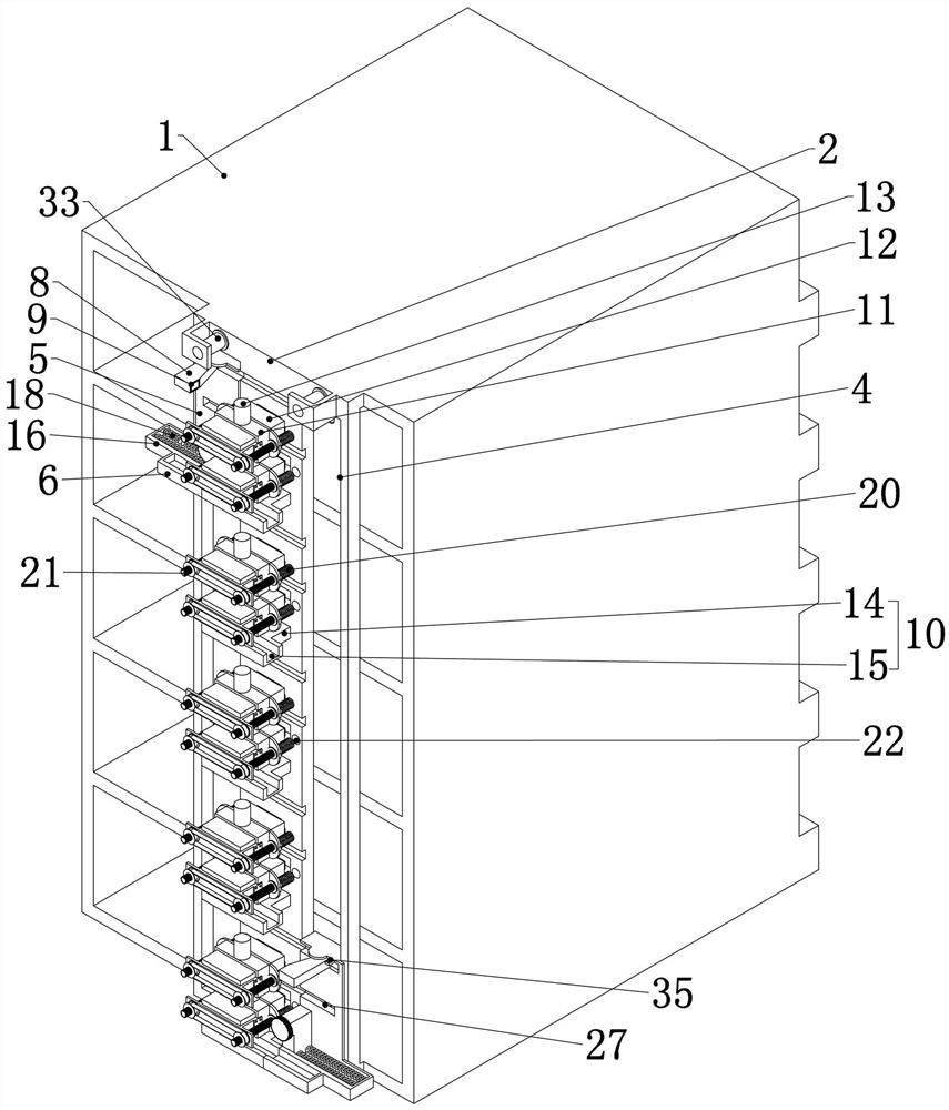
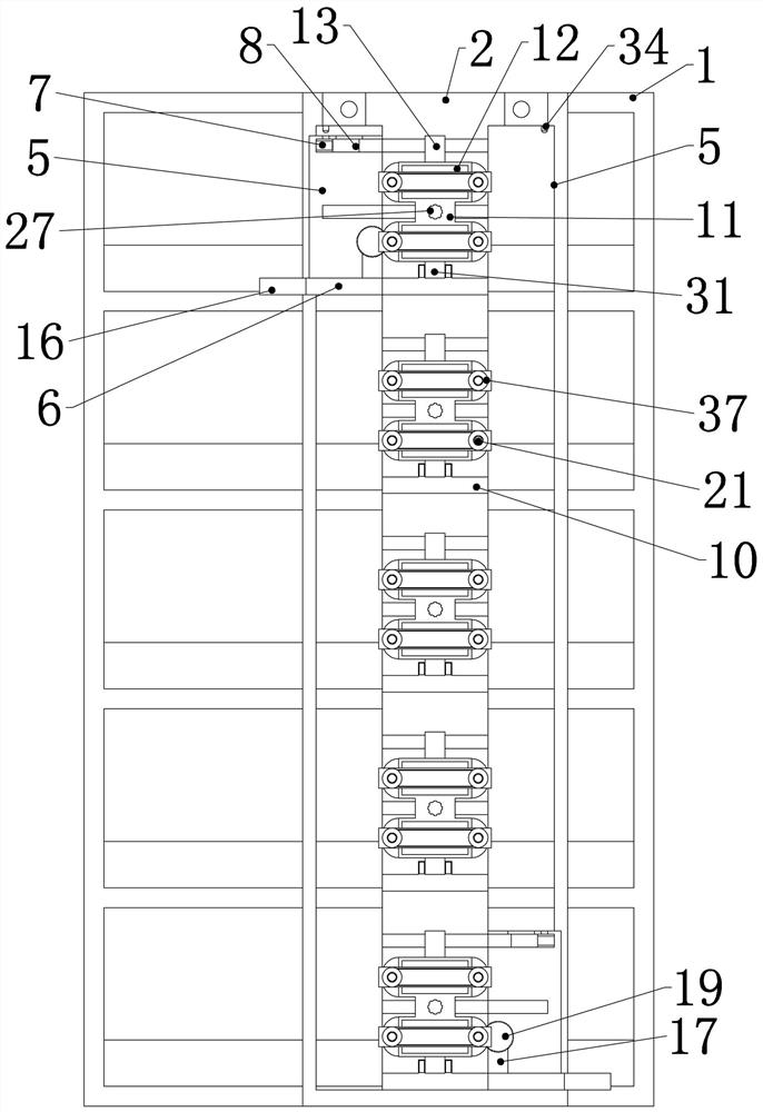
[0047]Embodiment 1. The present invention is a security protection interface device for a cloud computing platform, which includes a multi-layer cabinet 1. The cabinet 1 is a common cabinet 1. Servers are placed on each floor of the cabinet 1. The cabinet 1 is a common The server cabinet 1 is used to provide a fixed foundation for the subsequent structure. It is characterized in that, one end of the cabinet 1 is fixedly connected with a socket board 2, the socket board 2 is arranged at one end of the server interface, and each layer of the cabinet 1 is far away from the socket board 2. The fixed connection is a limiting plate, so as to prevent the server from falling from the cabinet 1. The socket plate 2 is evenly provided with a number of sockets 3, and the line connector 12 can pass through the socket 3 and be connected with the interface of the server. Several sockets 3 Evenly distributed from top to bottom and aligned up and down, some of the sockets 3 are provided with ve...

Embodiment 2

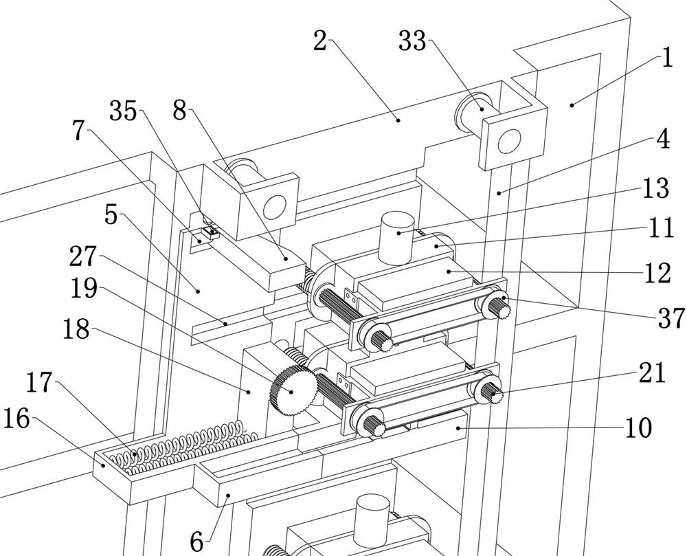
[0062] Embodiment 2. On the basis of Embodiment 1, a rotating shaft chute 25 is provided in the middle of the joint base 11, and the rotating shaft chute 25 is a cylindrical through groove. The rotating shaft chute 25 is slidingly connected with a rotating Axis 26, ref. Figure 7 , Figure 8 , the rotating shaft 26 can slide along the axial direction of the rotating shaft chute 25, and at the same time, the rotating shaft chute 25 cooperates with the keyway of the rotating shaft 26, so that the rotation of the rotating shaft 26 can drive the rotating shaft chute 25 to rotate synchronously, thereby driving the joint base 11 to rotate ;

[0063] The socket plate 2 is provided with a rotating shaft rail 27, and one end of the rotating shaft 26 is slidably connected in the rotating shaft rail 27. When the wedge block 8 drives the joint base 11 to slide along the interface rail 15, it rotates The shaft 26 slides in the rotating shaft cross rail 27, and one end of the rotating sha...

Embodiment 3

[0074] Embodiment 3, on the basis of Embodiment 1, one side of the interface horizontal rail 15 is fixedly connected with two electric telescopic rods 32 respectively placed on both sides of the interface vertical rail 14, and the two electric telescopic rods 32 can be respectively called It is the left electric telescopic rod 32 and the right electric telescopic rod 32, and the two electric telescopic rods 32 are all electrically connected with the control module, refer to Figure 9 , when the left transposition base 5 moves to the side of the socket 3, the control module simultaneously controls the extension of the right electric telescopic rod 32, and when the right transposition base 5 moves to the side of the socket 3, the control module simultaneously controls the left electric telescopic rod The rod 32 is extended.


PUM


Abstract

The invention relates to a safety protection interface device for a cloud computing platform, and effectively solves the problems that in the prior art, a server and different nodes are not used, automatic exchange connection cannot be achieved, and transmission efficiency is affected by line change after a transmission line and a connector break down. According to the technical scheme, the devicecomprises a multi-layer cabinet, a socket plate is fixedly connected to one end of the cabinet, a plurality of sockets are evenly formed in the socket plate, vertical rails arranged on the socket plate are arranged on the two sides of the sockets, transposition bases are connected into the two vertical rails in an up-down sliding mode, and base transverse rails are fixedly connected to the lowerends of the two transposition bases; multi-stage telescopic rods are fixedly connected to the upper ends of the two transposition bases, wedge-shaped blocks slidably connected to the corresponding transposition bases are fixedly connected to one ends of the two multi-stage telescopic rods, and electromagnets are fixedly connected to one ends of the two wedge-shaped blocks. The device is ingeniousin structure, convenient to control, capable of effectively achieving cross connection and data transmission between different servers and different nodes, and high in practicability.

Description

technical field [0001] The invention relates to the technical field of server protection, in particular to a security protection interface device for a cloud computing platform. Background technique [0002] Cloud computing is a kind of distributed computing, which refers to decomposing a huge data calculation processing program into countless small programs through the network cloud, and then processing and analyzing these small programs through a system composed of multiple servers to obtain results and return to the user. In the early days of cloud computing, simply put, it was simple distributed computing, solving task distribution, and merging calculation results. Therefore, cloud computing is also called grid computing. Through this technology, the processing of tens of thousands of data can be completed in a very short period of time, so as to achieve powerful network services. [0003] Cloud computing has high requirements on the server, and it needs to process a ...

Claims


Application Information

Patent Timeline
Patent Type & Authority Applications(China)
IPC IPC(8): G06F1/18H01R13/629H01R13/639
CPCG06F1/186H01R13/629H01R13/639H01R2201/06
Inventor 李克锋
Owner NANYANG MEDICAL COLLEGE
Why Eureka
Try Eureka