A rotor noise microphone array

A microphone array and microphone technology, which is applied in the direction of aircraft component testing, etc., can solve problems such as low operating efficiency, affecting work efficiency, and untrue data, and achieve the effects of saving costs, improving work efficiency and economic benefits, and improving work efficiency

Active Publication Date: 2022-06-21
CHINA HELICOPTER RES & DEV INST
View PDF0 Cites 0 Cited by
  • Summary
  • Abstract
  • Description
  • Claims
  • Application Information

AI Technical Summary

Problems solved by technology

[0007] 2. Higher height
[0008] 3. Frequent disassembly and assembly
During the test, the airflow turbulence caused by the rotation of the model rotor will cause the movement of the microphone cable, which will lead to unrealistic data
[0011] According to the conventional design, the microphone array can only be a special equipment for the noise test of a certain model rotor, which is not universal. For the model rotors with different diameters, the corresponding microphone array must be designed one-to-one; In the test phenomenon, it is necessary to increase the microphone at a specific position, so the microphone array usually adopts a redundant design of multiple rods, which affects the quality of the free sound field; Operators are hoisted to the corresponding height for high-altitude operations, which is inefficient and poses safety risks
In addition, it is necessary to cut the tape and tape during calibration and debugging, and to tie the tape and tape when restoring the installation, which not only affects work efficiency, but also causes unnecessary waste

Method used


Image

  • A rotor noise microphone array
  • A rotor noise microphone array
  • A rotor noise microphone array

Examples


Embodiment Construction

[0039] The technical solutions in the embodiments of the present invention will be clearly and completely described below with reference to the accompanying drawings in the embodiments of the present invention. Obviously, the described embodiments are only a part of the embodiments of the present invention, but not all of the embodiments. Based on the embodiments of the present invention, all other embodiments obtained by those of ordinary skill in the art without creative efforts shall fall within the protection scope of the present invention.

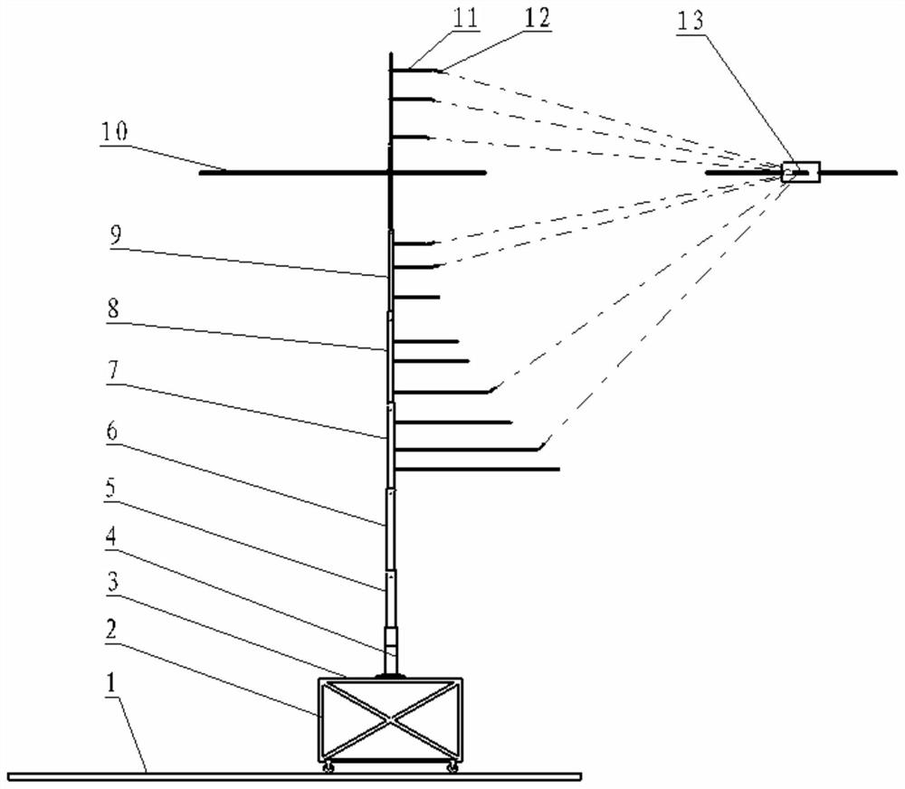
[0040] like figure 2 As shown, the movable operating platform 2 can slide forward and backward on the floor rail 1 of the anechoic chamber through four rollers. The rollers have a locking function. Once the distance between the microphone and the center of the propeller hub is determined, the rollers are locked. The microphone array no longer moves. The staff can stand on the mesh surface 3 of the operating platform to operate, 3 is...


PUM


Abstract

The invention belongs to the helicopter rotor test technology, and discloses a rotor noise microphone array, comprising: a plurality of microphones, a movable operating platform, a bottom support seat, N section vertical rods and M section horizontal bars; rollers are arranged under the movable operation platform For horizontal movement, a detachable mesh plane is set on the upper surface of the movable operating platform, and the mesh plane is used as the operating platform when disassembling the acoustic array, and the mesh plane is removed during the test to reduce the sound reflection; the lower part of the movable operating platform There are rollers for horizontal movement to adjust the overall distance of the microphone array relative to the rotor shaft; the bottom support base is fixed on the upper surface of the movable operating platform to support the sound array, and the first vertical rod of the N-section vertical rod is fixed on the On the bottom support base, the bottoms of the second to N sections of vertical bars are fixedly connected to the top of the previous section of vertical bars in turn; the M-section horizontal bar is connected to the N-section vertical bar through quick-release joints; multiple microphones are fixed at the end of the M-section horizontal bar; Where N and M are non-zero natural numbers.

Description

technical field [0001] The invention belongs to the technical field of helicopter rotor testing, in particular to a rotor noise microphone array. Background technique [0002] Rotor noise is one of the main noise sources of helicopters and an important object of helicopter noise reduction. Accurate and efficient model rotor noise tests are the premise of rotor noise reduction, and anechoic chamber tests are currently the main rotor noise test methods. In the anechoic chamber test, the rotor noise microphone array is an indispensable device, which is very important for capturing and identifying the noise source with complex distribution in the plane of the propeller disk, and analyzing the noise generation and attenuation history. [0003] As a commonly used tool for measuring the spatial distribution of sound sources, the microphone array is an array composed of several microphones arranged in a specific manner. Considering the directionality of rotor noise propagation, the ...

Claims


Application Information

Patent Timeline
Patent Type & Authority Patents(China)
IPC IPC(8): B64F5/60
CPCB64F5/60
Inventor 白莉马峰涛
Owner CHINA HELICOPTER RES & DEV INST
Why Eureka
Try Eureka