
An Axially Floating Backflow Annular Combustion Chamber Large Elbow Structure

An annular combustion chamber and floating technology, applied in the direction of combustion chambers, continuous combustion chambers, combustion methods, etc., can solve the problems of short service life of large elbows and inability to adjust the inner wall of large elbows independently, so as to increase service life and improve Service life, effect of reducing temperature gradient

Active Publication Date: 2022-02-11
SICHUAN AEROSPACE ZHONGTIAN POWER EQUIP CO LTD
View PDF0 Cites 0 Cited by
  • Summary
  • Abstract
  • Description
  • Claims
  • Application Information

AI Technical Summary

Problems solved by technology

[0006] The purpose of the present invention is to provide an axially floating backflow annular combustion chamber large elbow structure to solve the problem that the existing cooling method cannot independently adjust the temperature of the inner wall of the large elbow according to different working conditions of the engine. The defect of short service life

Method used


Image

  • An Axially Floating Backflow Annular Combustion Chamber Large Elbow Structure
  • An Axially Floating Backflow Annular Combustion Chamber Large Elbow Structure
  • An Axially Floating Backflow Annular Combustion Chamber Large Elbow Structure

Examples


Embodiment 1

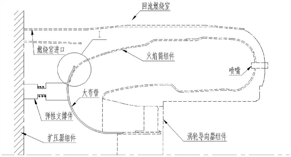
[0033] Such as Figure 3-5 As shown, an axially floating backflow annular combustion chamber large elbow structure includes a diffuser assembly, a flame tube assembly, and a turbine guide assembly. The diffuser assembly is provided with a plurality of elastic supports. A large curved pipe is arranged between the elastic support and the flame tube assembly, the central axis of each elastic support passes through the maximum point of the curvature of the large curved pipe, and the large curved pipe is fixed on the turbine guide On the device assembly, a cooling gap is formed between the large bend pipe and the flame tube assembly.

[0034]In the technical solution of the present application, the elastic support is installed on the diffuser assembly, and the large elbow is installed on the turbine guide assembly. The elastic support has no fixed connection with the large elbow, and is only in surface contact with the large elbow. In order to limit the axial expansion and contrac...

Embodiment 2

[0037] Such as Figure 3-5 As shown, on the basis of Embodiment 1, the flame tube assembly includes a flame tube outer shell and a flame tube inner shell, and the large bend coincides with the rear wall of the flame tube shell and forms the cooling gap. The large curved pipe is partially attached to the wall surface of the rear part of the flame tube shell, and the shape of the attached part is consistent.

Embodiment 3

[0039] Such as Figure 3-5 As shown, on the basis of Embodiment 1 or 2, the range of the cooling gap is 0-1.5mm. More preferably, the cooling gap may be 0mm, 0.2mm, 0.4mm, 0.6mm, 0.8mm, 1mm, 1.2mm, 1.3mm, 1.5mm.


PUM


Abstract

The invention discloses a large elbow structure of an axially floating type recirculation annular combustion chamber, which belongs to the field of aerodynamics, and specifically relates to the field of miniature recirculation annular combustion chambers, in order to solve the existing problem that the self-regulation cannot be realized according to different working conditions of the engine. The temperature defect of the inner wall of the large elbow includes a diffuser assembly, a flame tube assembly, and a turbine guide assembly. The diffuser assembly is provided with a plurality of elastic supports, and the gap between the elastic support and the flame tube assembly is A large curved pipe is provided, and the large curved pipe is fixed on the turbine guide assembly, and a cooling gap is formed between the large curved pipe and the flame tube assembly. The large elbow and the flame tube assembly are set separately, and at the same time, the elastic support is in surface contact with the large elbow, so that a cooling gap is formed between the large elbow and the flame tube assembly. The cooling air entering different gap values ​​is different, and the cooling effect is different. The effect of independently adjusting the temperature of the inner wall of the big bend is realized, and the service life of the big bend is increased at the same time.

Description

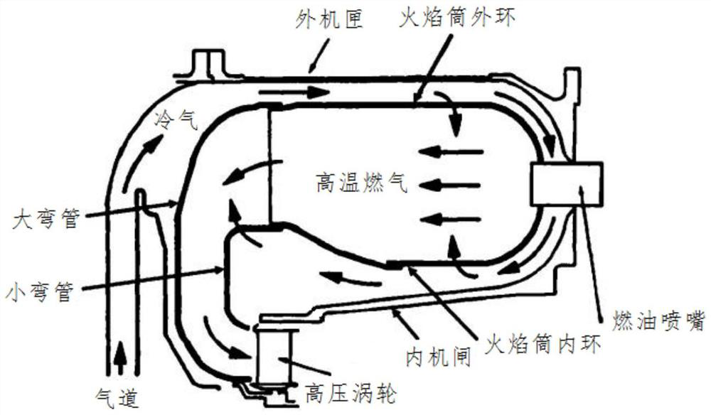
technical field [0001] The invention relates to a large elbow structure of an axially floating type recirculation annular combustion chamber. The invention belongs to the technical field of aerodynamics, and in particular relates to the technical field of a gas turbine engine miniature recirculation annular combustion chamber. Background technique [0002] In order to meet the future development needs of armed helicopters, weaponry and auxiliary power units, the performance of aero turbine engines has also been continuously improved. Since the 1980s, the combustion chambers of small engines generally adopt backflow combustion chambers. In the once-through combustor, the air passes through the flame tube directly, and the flow direction from the inlet to the outlet is basically unchanged. In the recirculation combustion chamber, the gas flow is completely different, figure 1 A schematic diagram of gas flow in a recirculation annular combustor is given. The high-pressure ai...

Claims


Application Information

Patent Timeline
Patent Type & Authority Patents(China)
IPC IPC(8): F23R3/52F23R3/60
CPCF23R3/52F23R3/60F23R2900/03043
Inventor 曾凡李纪永李芳陈亮胡凯王丹丹
Owner SICHUAN AEROSPACE ZHONGTIAN POWER EQUIP CO LTD
Learn More