Spiral heat exchanger

A heat exchanger, spiral type technology, applied in the direction of heat exchanger type, heat exchanger shell, indirect heat exchanger, etc., can solve the problem of large flow resistance, affecting thermal fluid transportation, reducing heat exchange area of ​​heat exchanger, etc. Problems, achieve uniform discharge temperature and exhaust temperature, increase liquid flow and heat transfer capacity, and increase the effect of installation space

Pending Publication Date: 2021-02-19
SHANGHAI XINGYE MATERIALS TECH CO LTD
View PDF1 Cites 1 Cited by
  • Summary
  • Abstract
  • Description
  • Claims
  • Application Information

AI Technical Summary

Problems solved by technology

The hot fluid and the cold fluid move in the hot fluid channel and the cold fluid channel respectively along the helical curling direction for a long distance. During the movement, the moving direction of the fluid is changing all the time, and there will be a large interaction between the thin plate and the heat exchange fluid. Force, so that the flow resistance of the fluid in the flow channel is relatively large, which is not suitable for heat exchange of gaseous fluids
[0005] 2. High maintenance frequency
Taking the hot fluid flow channel as an example, the problem with a single flow channel is that if a certain position of the hot fluid flow channel is blocked, it will affect the transportation of the hot fluid in the entire hot fluid flow channel. The heat exchanger cannot work normally, that is, as long as there is a blockage in the hot fluid flow channel, the staff will need to maintain the heat exchanger, and the maintenance frequency is high
[0006] 3. This heat exchanger is a multi-layer spiral wound structure. In order to perform sufficient heat exchange and obtain high heat exchange efficiency, the structure usually winds multiple layers, making the radial dimension too large. When the heat exchanger is installed When the heat exchanger is installed, it is necessary to provide a large radial space for installing the heat exchanger, which cannot realize the concealed installation of the heat exchanger in some occasions where the radial space is limited
[0007] 4. As mentioned above, in order to perform sufficient heat exchange and obtain higher heat exchange efficiency, the structure is usually wound with multiple layers to increase the internal fluid movement stroke, and because of the spiral flow channel, the internal resistance is large, so the When clogged, the clog is extremely difficult to clear
If the fluid flow rate is increased by increasing the cross-sectional area of ​​the spiral flow channel, the heat exchange area of ​​the heat exchanger of the same size will be greatly reduced

Method used


Image

  • Spiral heat exchanger
  • Spiral heat exchanger
  • Spiral heat exchanger

Examples


Embodiment 1

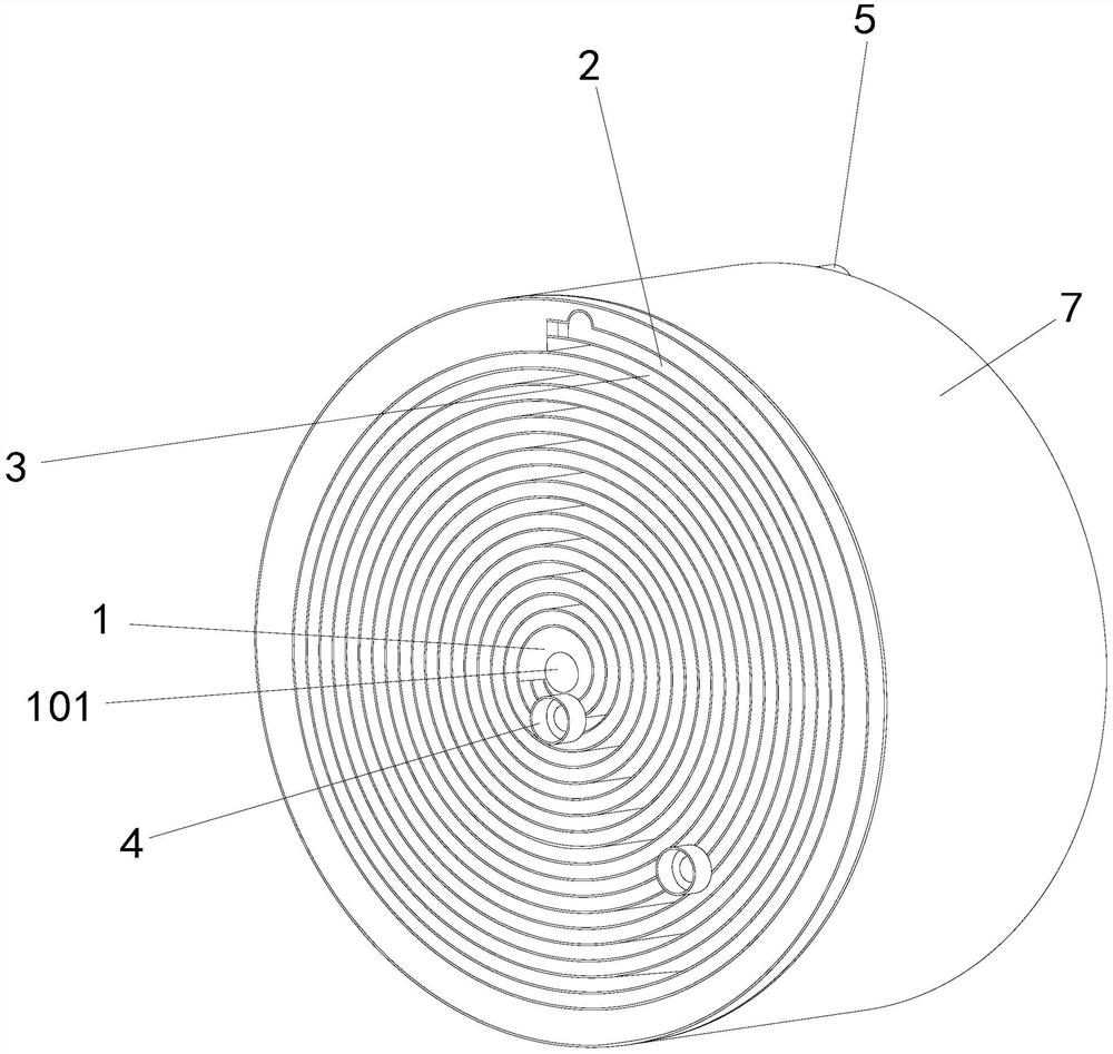
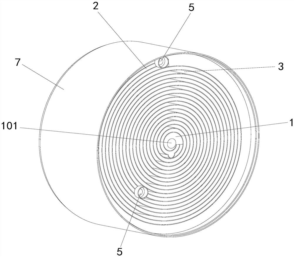
[0058] Figure 1 to Figure 6 Shown is the first specific embodiment of the spiral heat exchanger, which is mainly composed of a mandrel 1 and a liquid-feeding coil 2 . Wherein the liquid-feeding tape 2 is spirally wound on the periphery of the mandrel 1, and the winding number of the liquid-feeding tape 2 is ten turns, so that a spiral with ten helical layers is formed in the liquid-feeding tape 2 Liquid channel 201 . In order to describe the specific structure of the spiral heat exchanger more conveniently, the length direction of the mandrel 1 is now defined as the left-right direction, that is, the axis of the mandrel 1 extends left and right (extends from left to right).

[0059] In this embodiment, any two adjacent coil layers of liquid-feeding coils 2 are separated by a certain distance, thereby forming a spiral-shaped air-flowing channel 3 penetrating left and right. In order to prevent the liquid-feeding coils 2 of adjacent circles from abutting against each other, t...

Embodiment 2

[0072] Figure 8 and Figure 9 The second specific embodiment of the spiral heat exchanger is shown, which has a structure similar to that of the first embodiment, except that:

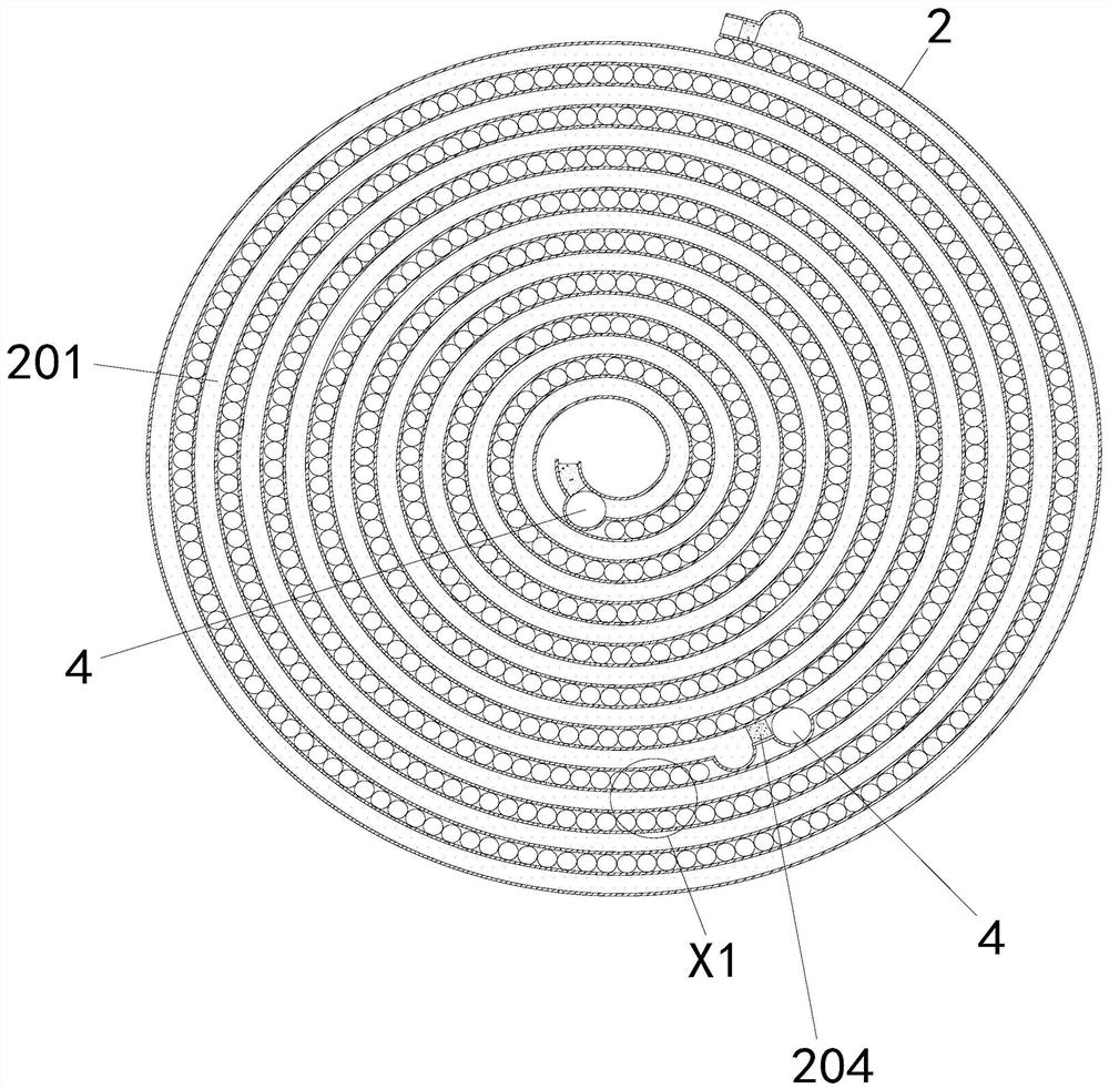
[0073]There is not only one liquid channel separating bar 204 provided in the liquid-carrying coiled strip 2, but many. The length of each liquid channel separating strip 204 extends left and right, and these liquid channel separating strips 204 are arranged at intervals along the spiral direction of the liquid carrying coil 2 . These liquid channel separation strips 204 divide the spiral liquid channel 201 into a plurality of liquid flow sub-channels 201a arranged in sequence along the helical direction of the liquid-carrying coil 2 and isolated from each other. Each liquid flow channel 201a is provided with a first liquid inlet and outlet port 4 at the inner end in the helical direction (that is, the length direction), and each liquid flow channel 201a is provided with a first liquid inlet port 4 ...

Embodiment 3

[0077] Figure 10 and Figure 11 Shown is a third specific embodiment of the spiral heat exchanger, which has a structure similar to that of Embodiment 1, the difference being:

[0078] The heat exchanger of this application is equipped with two liquid-feeding coils, one of which is spirally wound around the mandrel 1, and the number of coils is about 7. Another liquid-feeding tape 2 is spirally wound around the periphery of the first liquid-feeding tape 2, and the number of winding turns is about 3. For the convenience of description, the inner liquid-feeding coil 2 is called the first liquid-feeding coil, and the spiral liquid channel 201 formed in it is called the first spiral liquid channel; the outer liquid-feeding coil 2 is called the second The second liquid-carrying coil, the spiral liquid channel 201 formed in it is called the second spiral liquid channel. The first liquid-carrying coils of any two adjacent circles are separated by a certain distance, thereby formi...


PUM


Abstract

The invention relates to a spiral heat exchanger. The spiral heat exchanger comprises a mandrel with the axis extending leftwards and rightwards, and liquid flowing winding belts which are spirally wound around the periphery of the mandrel by at least two circles and internally provided with spiral liquid channels; and the liquid flowing winding belts of any two adjacent ring layers are spaced bya certain distance, so that a spiral air flowing channel which is through left and right is formed, a liquid channel separation strip which extends left and right is arranged in each liquid flowing winding belt, the liquid channel separation strips separate the spiral liquid channels into a plurality of liquid flow branch channels which are sequentially arranged in the spiral direction and are isolated from one another, the inner side end and the outer side end of each liquid flow branch channel in the spiral direction are provided with a first liquid inlet and outlet connector and a second liquid inlet and outlet connector respectively, wherein the first liquid inlet and outlet connectors and the second liquid inlet and outlet connectors are in communication through the liquid flow branchchannels. The heat exchanger is large in heat exchange amount and high in heat exchange efficiency.

Description

technical field [0001] The application relates to the field of heat exchange, in particular to a spiral heat exchanger. Background technique [0002] Heat exchanger refers to the equipment that transfers the heat of hot fluid to cold fluid. Heat exchanger has important applications in life and industrial production. Due to the pursuit of larger heat exchange area, traditional heat exchangers generally occupy a large area , so it has the disadvantages of high requirements for installation space and inconvenient maintenance. Therefore, on the premise of ensuring sufficient heat exchange area, how to reduce the volume of the heat exchanger is an urgent problem to be solved in the industry. [0003] The Chinese utility model patent with the patent number CN201520085162.X discloses a new type of spiral plate reaction heat exchanger, including a first thin plate, a second thin plate, an intermediate partition and an outer cylinder, wherein the first thin plate and the second thin...

Claims


Application Information

Patent Timeline
Patent Type & Authority Applications(China)
IPC IPC(8): F28D9/04F28F9/00F28F27/00
CPCF28D9/04F28F9/00F28F27/00
Inventor 高峰刘在祥陈艳凤蔡园丰王兵牛争艳
Owner SHANGHAI XINGYE MATERIALS TECH CO LTD
Why Eureka
Try Eureka