Eureka AIR delivers breakthrough ideas for toughest innovation challenges, trusted by R&D personnel around the world.

Transformer gas relay pipeline structure

A gas relay and transformer technology, applied in transformer/inductor parts, electrical component structure associations, circuits, etc., can solve problems such as spending a few days, and achieve the effect of high utilization, simple production, and easy maintenance.

Pending Publication Date: 2021-02-19
WUJIANG TRANSFORMER
View PDF0 Cites 0 Cited by
  • Summary
  • Abstract
  • Description
  • Claims
  • Application Information

AI Technical Summary

Problems solved by technology

Usually, in order to ensure the quality of the main protection equipment of the transformer, the gas relay, it is necessary to carry out preventive testing on it; Disassemble it and send it to an authoritative professional testing organization for maintenance or calibration. This method usually takes a few days, especially in remote mountainous areas where the transformer installation site is far away from the gas relay testing unit and the transportation is inconvenient.

Method used


Image

  • Transformer gas relay pipeline structure

Examples


Embodiment

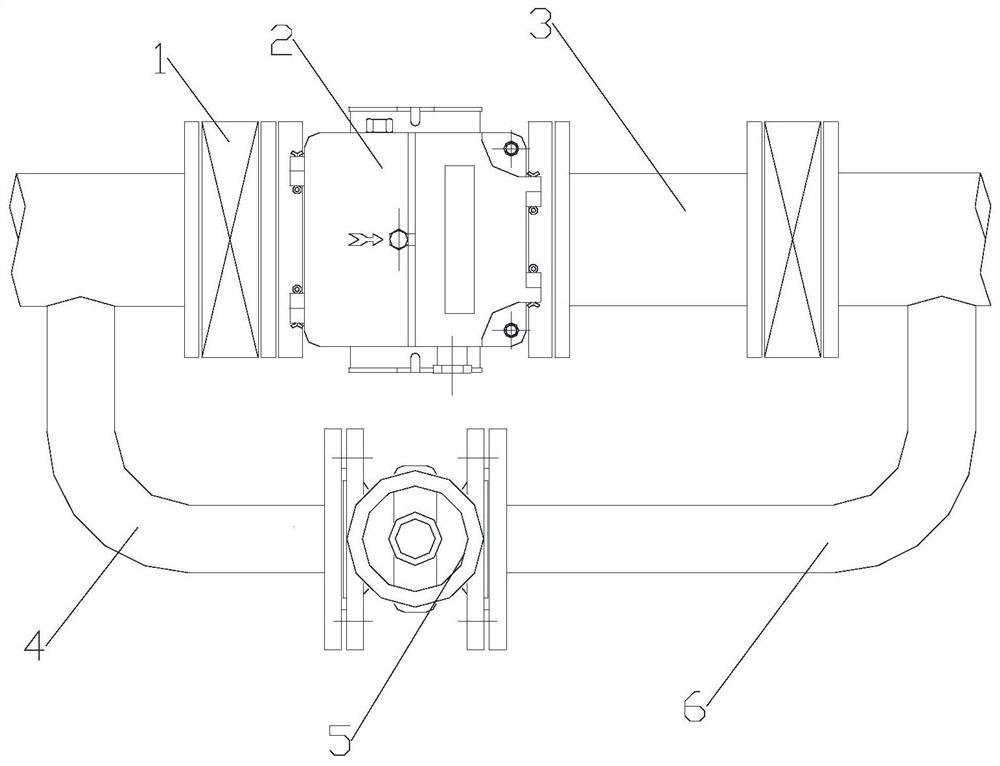
[0011]Such asfigure 1As shown, a pipeline structure at a transformer gas relay includes a gas relay 2, a DN80 butterfly valve 1 and a ZF50 gate valve 5; the two ends of the gas relay 2 are respectively connected to the transformer main gas collecting pipeline through a DN80 butterfly valve 1; The two ends of the ZF50 gate valve 5 are connected in parallel to the two ends of the gas relay 2 through the first pipe joint 4 and the second pipe joint 6 respectively.

[0012]Based on the above, the two DN80 butterfly valves 1 are located between the interface of the first pipe joint 4 and the main air collector of the transformer and the interface of the second pipe joint 6 and the main air collector of the transformer.

[0013]The first pipe joint 4 is welded to the main gas collector at the back end of the gas relay 2. A DN80 butterfly valve 1 is designed between the welding point and the gas relay 2; the second pipe joint 6 is welded to the main gas collector at the front end of the gas rela...


PUM


Abstract

The invention relates to the technical field of transformers, and discloses a transformer gas relay pipeline structure which comprises a gas relay, a DN80 butterfly valve and a ZF50 gate valve. Two ends of the gas relay are respectively connected to a main gas collecting pipeline of the transformer through a DN80 butterfly valve. The two ends of the ZF50 gate valve are connected to the two ends ofthe gas relay 2 in parallel through a first pipe connector and a second pipe connector respectively. And the two DN80 butterfly valves are positioned between the interface of the first pipe joint andthe transformer main gas collecting pipe and the interface of the second pipe joint and the transformer main gas collecting pipe. A side pipeline is designed for the gas relay on the main gas collecting pipe of the transformer and at the position of the gas relay, when the routine check time of the gas relay expires or the gas relay is found to be abnormal in the operation process of the transformer, the gas relay can be detected under the condition that the transformer is not powered off, the inspection time is sufficient. Therefore, the gas relay can be ensured to be comprehensively overhauled and verified.

Description

Technical field[0001]The invention relates to a pipeline for transformer protection, in particular to a pipeline structure at a transformer gas relay.Background technique[0002]With the rapid development of my country's national economy, continuous operation of high-voltage, large-capacity transformers is very necessary. In order to ensure the continuous continuous operation of the transformer, the quality of the transformer product should be ensured first; secondly, the load rate and operating time should be determined according to the transformer technical parameters and operating conditions. There are many factors that determine the quality of transformer products, among which internal factors involve materials, design, technology, manufacturing, etc., and external factors mainly include accessory quality, reliability, and sensitivity. Generally, in order to ensure the quality of the main protection equipment of the transformer-gas relay, it is necessary to conduct preventive test...

Claims


Application Information

Patent Timeline
Patent Type & Authority Applications(China)
IPC IPC(8): H01F27/40
CPCH01F27/40H01F27/402
Inventor 董景义李国旗费旭城周彬
Owner WUJIANG TRANSFORMER
Why Eureka
Eureka Blog
Learn More