Feather removing device for poultry slaughtering

A depilation device and technology for poultry, which are applied to poultry plucking machines, poultry processing, slaughtering and other directions, can solve problems such as low depilation efficiency, and achieve the effects of improving depilation effect, improving depilation efficiency, and maintaining cleanliness.

Inactive Publication Date: 2021-02-23
刘福娟
View PDF0 Cites 1 Cited by
  • Summary
  • Abstract
  • Description
  • Claims
  • Application Information

AI Technical Summary

Problems solved by technology

[0004] Based on the technical problem of low hair removal efficiency of existing devices, the present invention proposes a hair removal device for poultry slaughter

Method used


Image

  • Feather removing device for poultry slaughtering
  • Feather removing device for poultry slaughtering
  • Feather removing device for poultry slaughtering

Examples


Embodiment 1

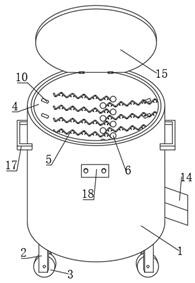
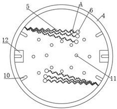
[0031] refer to Figure 1-5 A depilatory device for poultry slaughtering, comprising a box body 1, a plurality of legs 2 are symmetrically fixed on both sides of the bottom of the box body 1 by bolts, rollers 3 are fixed on the bottom of the legs 2 by bolts, and the top of the box body 1 is connected by hinges. Cover plate 15, the top of cover plate 15 is fixed with a first handle 16 by bolts, the bottom of the inner wall of box body 1 is welded with a fixed seat 7, the top of fixed seat 7 is fixed with a motor 8 by bolts, and a drum 4 is arranged above the motor 8, and the drum 4 A mounting plate 9 is welded at the bottom, and the bottom of the mounting plate 9 is fixedly connected to the output shaft of the motor 8. Both sides of the drum 4 are fixed with a plurality of springs 5 ​​distributed up and down by bolts. The inside of the spring 5 is welded with a counterweight ball 6. The spring 5 is relatively arranged, and the interior of the spring 5 is welded with a plurality...

Embodiment 2

[0035] refer to Figure 1-7 , a hair removal device for poultry slaughter, the top of the cover plate 15 is fixed with a fan 19 by bolts, the exhaust end of the fan 19 is connected with a connecting pipe 20, the connecting pipe 20 and the cover plate 15 are fixed through, and the bottom of the connecting pipe 20 is connected with a wind pan 21, The bottom of the cover plate 15 is provided with a mesh cover 22, the cross section of the mesh cover 22 is set in the shape of a cat face, the mesh cover 22 is arranged on the periphery of the wind disk 21, the bottom of the cover plate 15 is provided with a ring groove 23, and the ring groove 23 is arranged on the periphery of the wind disk 21, Two sliders 24 are slidably connected in the ring groove 23, and the bottoms of the two sliders 24 are fixedly connected with the net cover 22 by bolts. The top of the slider 24 is provided with a plurality of circular grooves, and balls 25 are movably connected in the circular grooves. , the ...


PUM


Abstract

The invention belongs to the technical field of poultry slaughtering, particularly relates to a feather removing device for poultry slaughtering, and aims to solve a problem that an existing device islow in feather removing efficiency. The device comprises a box body, wherein a fixing base is welded to a bottom of an inner wall of the box body, a motor is fixed on a top of the fixing base, a rotary drum is arranged above the motor, a mounting plate is welded to a bottom of the rotary drum, a bottom of the mounting plate is fixedly connected with an output shaft of the motor, a plurality of springs which are distributed up and down are fixed to two sides of the rotary drum through bolts, balance weight balls are welded to inner sides of the springs, the springs on two sides are oppositelyarranged, the springs have different angles with the vertical direction, and elastic coefficients of the springs are different, a thick feather removing mechanism is provided in the rotary drum, and adischarging mechanism is arranged at a bottom of the box body. According to the device, an output shaft of the motor drives the rotary drum to rotate, then the springs and the balance weight balls are driven to rotate, when the springs are stretched, thick feathers are clamped by the springs, thin feathers are clamped by two clamping pieces, and therefore feather removal efficiency is effectivelyimproved.

Description

technical field [0001] The invention relates to the technical field of poultry slaughter, in particular to a depilatory device for poultry slaughter. Background technique [0002] Poultry is a general term for artificially raised birds. It is generally pheasant and duck, such as chicken, duck, goose, etc., and there are also birds of other families such as turkey, pigeon, quail and various songbirds. Breeding is mainly to obtain its meat, eggs and feathers, and also for viewing and other purposes. As known, in the prior art, when poultry is processed, it needs to go through processes such as corona, slaughter, depilation, and decomposition. [0003] Because the feathers of poultry are distributed all over the body, it is difficult to clean and completely remove. The traditional method is to manually extract and clean and depilate each surface of the poultry one by one. The depilation efficiency is extremely slow, and because the feathers carry a large number of bacteria , ...

Claims


Application Information

Patent Timeline
Patent Type & Authority Applications(China)
IPC IPC(8): A22C21/02
CPCA22C21/02A22C21/026
Inventor 刘福娟
Owner 刘福娟
Why Eureka
Try Eureka