Hot-pressing waste gas collection treatment device

A technology of waste gas collection and treatment device, applied in transportation and packaging, dispersed particle filtration, dispersed particle separation, etc., can solve problems such as environmental pollution, waste gas spillage, human injury, etc., and achieve the effect of avoiding environmental pollution

Active Publication Date: 2021-02-23
江苏丰昌机电科技有限公司
View PDF6 Cites 1 Cited by
  • Summary
  • Abstract
  • Description
  • Claims
  • Application Information

AI Technical Summary

Problems solved by technology

[0002] The molded door panel will generate a lot of hot-pressed exhaust gas during the hot-pressing molding process; most of the existing hot-pressing equipment is equipped with an exhaust gas collection cover on the top to collect the exhaust gas. Pollution will also cause harm to the human body;
[0003] In the post-processing of waste gas recovery, an independent filtration and adsorption treatment channel is generally set up, and the treatment system needs to be shut down during the replacement of the adsorption plate and maintenance, thereby reducing the production efficiency of hot pressing;

Method used


Image

  • Hot-pressing waste gas collection treatment device
  • Hot-pressing waste gas collection treatment device
  • Hot-pressing waste gas collection treatment device

Examples


Embodiment 1

[0025] Embodiment 1: as Figure 1-5 shown;

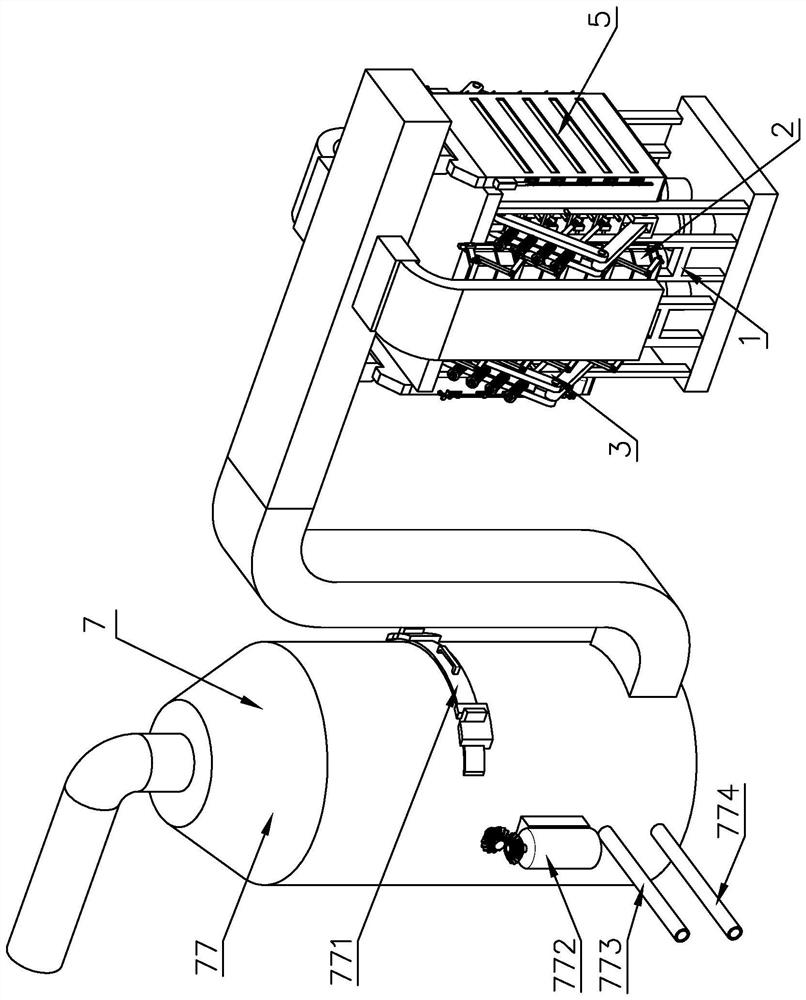
[0026] A hot-pressed waste gas collection and treatment device, comprising a frame 1, a first waste gas collection mechanism 2, a hot press mechanism 3, a second waste gas collection mechanism 5, and a filter tower 7; the frame 1 carries the first waste gas collection mechanism 2, the second Exhaust gas collection mechanism 5 and heat press mechanism 3; the first exhaust gas collection mechanism 2 is fixed on both sides of the frame 1; the second exhaust gas collection mechanism 5 is fixed on both ends of the frame 1; the heat press mechanism 3 is fixed inside the frame 1 Surrounded by a waste gas collection mechanism 2 and a second waste gas collection mechanism 5; the top of the frame 1 is provided with a top plate 12, and the bottom is provided with a base 11; the base 11 is provided with an oil cylinder 13; the top shaft of the oil cylinder 13 is connected to the heat-pressing mechanism 3.

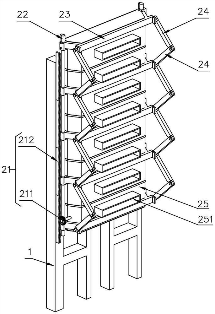
[0027] The first exhaust gas collec...

Embodiment 2

[0033] Embodiment 2: as Figure 6 Shown, compared with embodiment 1, the difference is:

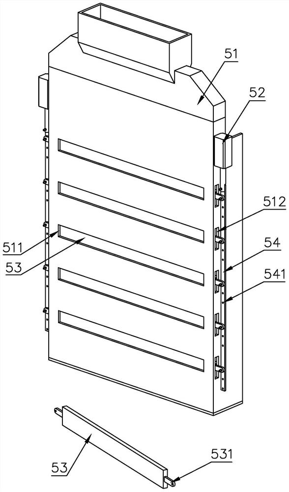
[0034] The two ends of the sealing plate 53 are provided with connecting arms II 532; the two sides of the cover plate 51 are respectively provided with a set of first lead screws 56 and bevel gears are arranged at both ends, and the first lead screws 56 pass through the connecting arms II 532 Threads are connected to each other; the top of the cover plate 51 is provided with a second lead screw 57 and both ends are provided with bevel gears and are meshed with the bevel gears at one end of the first lead screw 56; one end of one group of first lead screws 56 is provided with a motor I55 is fixed on the cover plate 51; the shaft end of the motor I55 is provided with a bevel gear meshing with the bevel gear at one end of the first lead screw 56; the power provided by the motor I55 drives the sealing plate 53 to move up and down along the first lead screw 56 to realize the feeding port 511 ...


PUM


Abstract

The invention discloses a hot-pressing waste gas collection and treatment device which comprises a rack, first waste gas collection mechanisms, a hot-pressing mechanism, second waste gas collection mechanisms and a filtering tower. The rack bears the first waste gas collection mechanisms, the second waste gas collection mechanisms and the hot pressing mechanism. The first waste gas collection mechanisms are fixed to the two sides of the rack. The second waste gas collecting mechanisms are fixed at two ends of the rack; the hot-pressing mechanism is fixed in the rack and surrounded by the firstwaste gas collecting mechanisms and the second waste gas collecting mechanisms; a top plate is arranged at the top of the rack, and a base is arranged at the bottom of the rack; an oil cylinder is arranged on the base; the oil cylinder top shaft is connected with the hot-pressing mechanism. On the premise that the hot-pressing production efficiency is not affected, the waste gas collection and treatment efficiency can be greatly improved.

Description

technical field [0001] The invention belongs to the technical field of waste gas collection and treatment, in particular to a hot-pressed waste gas collection and treatment device. Background technique [0002] The molded door panel will generate a lot of hot-pressed exhaust gas during the hot-pressing molding process; most of the existing hot-pressing equipment is equipped with an exhaust gas collection cover on the top to collect the exhaust gas. Pollution will also cause harm to the human body; [0003] In the post-processing of waste gas recovery, an independent filtration and adsorption treatment channel is generally set up, and the treatment system needs to be shut down during the replacement of the adsorption plate and maintenance, thereby reducing the production efficiency of hot pressing; [0004] Therefore, there is a need for a treatment device that can improve the efficiency of waste gas adsorption treatment without affecting the production efficiency of hot pre...

Claims


Application Information

Patent Timeline
Patent Type & Authority Applications(China)
IPC IPC(8): B01D46/00B01D53/04
CPCB01D53/04B01D46/56
Inventor 周为山
Owner 江苏丰昌机电科技有限公司
Why Eureka
Try Eureka