Pin header forming equipment for optical fiber connector and forming method thereof

A technology for optical fiber connectors and molding equipment, which is applied in grinding/polishing equipment, machine tools suitable for grinding the edge of workpieces, metal processing equipment, etc., and can solve cumbersome operations, low automation, and non-linkage between fixtures and polishing main parts And other issues

Active Publication Date: 2022-04-29
黄山市恒连电子科技有限公司
View PDF0 Cites 0 Cited by
  • Summary
  • Abstract
  • Description
  • Claims
  • Application Information

AI Technical Summary

Problems solved by technology

[0007] Third, local polishing needs to be fixed by a jig, but the jig and the polishing main part are not linked, the degree of automation is low, and the operation is cumbersome

Method used


Image

  • Pin header forming equipment for optical fiber connector and forming method thereof
  • Pin header forming equipment for optical fiber connector and forming method thereof
  • Pin header forming equipment for optical fiber connector and forming method thereof

Examples


Embodiment 1

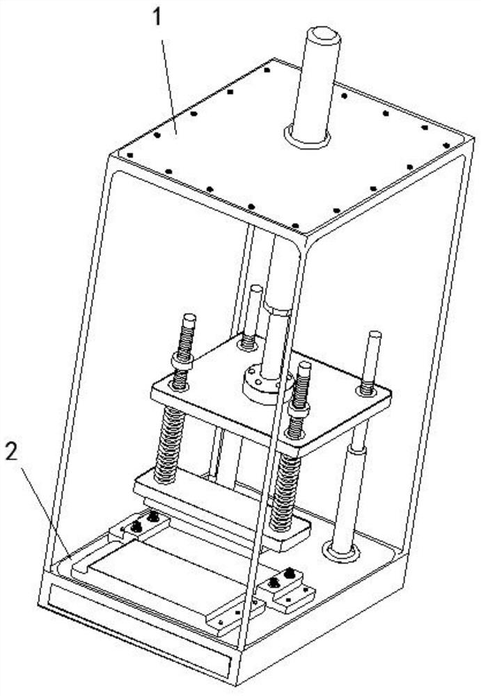
[0044] Such as Figure 1-6 As shown, the pin header forming equipment for optical fiber connectors includes a support frame 1 and a polishing main part 2; a supporting frame 1 is arranged above the polishing main part 2, and the supporting frame 1 is connected with the polishing main part 2 for supporting polishing Main piece 2.

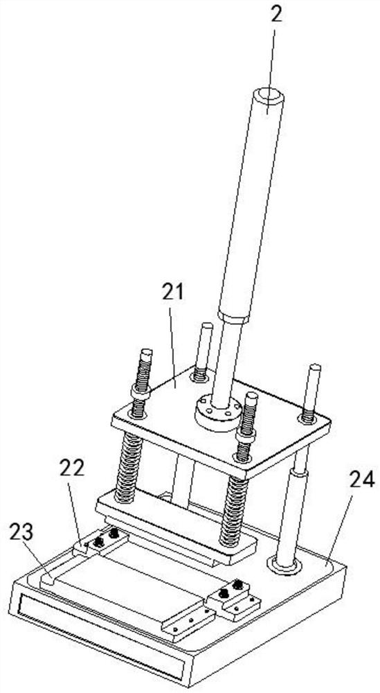
[0045] The polishing main part 2 includes a stamping assembly 21, and an isolation base 24 is provided under the stamping assembly 21. The isolation base 24 is plugged and connected with the stamping assembly 21, and is used to pump air into the isolation base 24. The stamping assembly 21 is connected to the support frame 1. The upper top phase is fixedly connected; the top of the isolation base 24 is provided with a material platform 22, and the material platform 22 is located below the stamping assembly 21, and is used for the stamping assembly 21 to be in contact with the material platform 22 during the plugging action relative to the isolation ba...

Embodiment 2

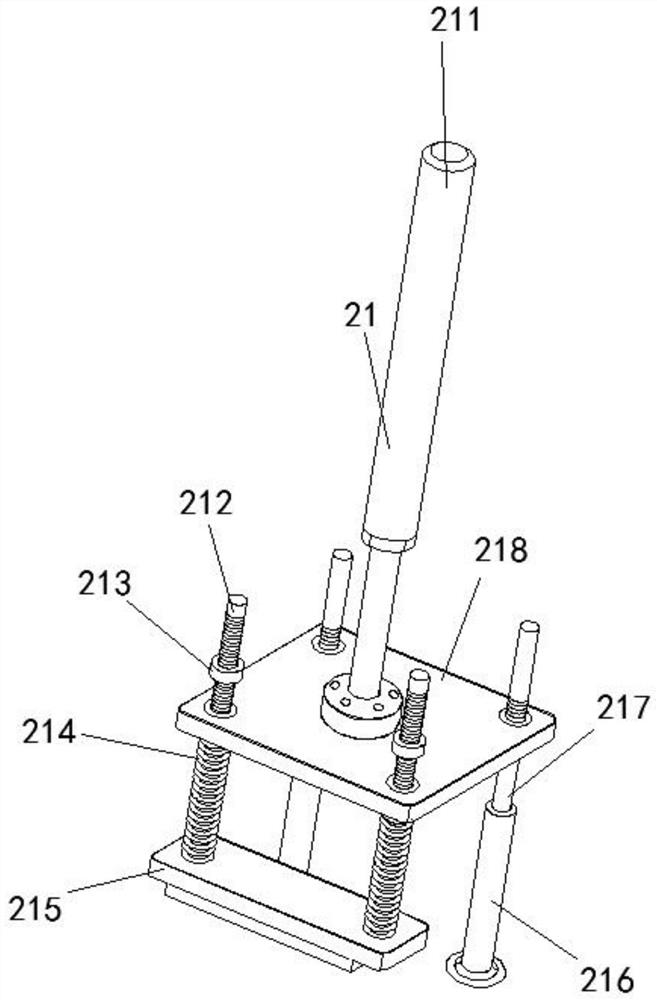
[0050] Such as Figure 1-6 As shown, the pin row forming equipment used for optical fiber connectors, the stamping assembly 21 includes a platen 218, the platen 218 is located above the isolation base 24 and is parallel to the isolation base 24, and the top of the platen 218 is provided with a pneumatic drive member perpendicular to it 211, the pneumatic drive part 211 is fixedly connected to the top of the support frame 1, the pneumatic drive part 211 includes a pneumatic sleeve and a drive rod, wherein the pneumatic sleeve is fixedly connected to the top of the support frame 1, and the drive rod is placed in the pneumatic sleeve , and its lower end is connected with the platen 218 for driving the platen 218 to move up and down.

[0051] A briquetting block 215 is arranged above the material table 22, and two parallel threaded rods 212 are arranged symmetrically on the top of the briquetting block 215. The threaded rods 212 are movably interspersed with the platen 218 and ext...

Embodiment 3

[0059] Such as Figure 1-6 As shown, the isolation base 24 includes a support box 242 for the needle row forming equipment for optical fiber connectors. The support box 242 is connected with the support frame 1 to form an integrated frame. Below the plate 241, a spacer 243 is arranged in the support box 242. The ends on both sides of the spacer 243 are fixed to the two ends of the support box 242, and are used to divide the inner cavity of the support box 242 into two. The top of the spacer 243 Contradicting against the bottom of the supporting plate 241, the separator 243 divides the inner cavity of the support box 242 into an air blowing cavity and a collecting cavity, and the grinding assembly 23 is inserted into the collecting cavity.

[0060] Wherein, the grinding assembly 23 includes a grinding medium box 234, the grinding medium box 234 is inserted into the support plate 241, and extends upward relative to the support plate 241, and a cover box 231 is arranged above the...


PUM


Abstract

The invention provides a pin header forming equipment for optical fiber connectors and a molding method thereof, and relates to the field of pin header molding equipment. The invention includes a support frame and a polishing main part; a supporting frame is arranged above the polishing main part, and the supporting frame is the same as the polishing element. The main parts are connected to support the polishing main part; the polishing main part includes a stamping assembly, an isolation base is arranged under the stamping assembly, and the isolation base is plugged and connected with the stamping assembly for pumping air into the isolation base, so The stamping assembly is fixedly connected to the upper top of the support frame; the top of the isolation base is provided with a material table, and the stamping assembly is not limited to the clamping function. When the assembly is connected to the isolation base, the air flow is blown into the grinding assembly, so that the grinding medium moves in the grinding assembly with high frequency in the blowing of the air flow, and the needle row inserted into the grinding assembly is polished.

Description

technical field [0001] The invention relates to the field of pin row forming equipment, in particular to a pin row forming device for optical fiber connectors and a forming method thereof. Background technique [0002] Pin headers are widely used in PCB circuit boards of electronics, electrical appliances, and instruments. Their function is to act as a bridge between blocked or isolated circuits in the circuit, and to undertake the task of current or signal transmission. It can be used together with the busbar to form a board-to-board connection, or used together with the electronic harness terminal to form a board-to-wire connection; it can also be used independently for board-to-board connection. [0003] During the needle header production, relying on the cutting equipment to cut off the metal contact strip at the pin header, after cutting, the cut surface of the needle header is polished based on the local polishing device, so as to avoid the unsightly appearance of the ...

Claims


Application Information

Patent Timeline
Patent Type & Authority Patents(China)
IPC IPC(8): B24B29/02B24B1/04B24B9/04B24B41/06B24B55/06B24B55/12B24B57/00
CPCB24B29/02B24B1/04B24B9/04B24B41/06B24B57/00B24B55/06B24B55/12
Inventor 丁小兵
Owner 黄山市恒连电子科技有限公司
Why Eureka
Try Eureka