Supercharge Your Innovation With Domain-Expert AI Agents!

A cable tightening device

A cable and wire roller technology, applied in the field of cable processing equipment, can solve the problems of inability to install and disassemble wire rollers and empty wire rollers, and inability to arrange cables, so as to achieve high efficiency, reduced labor intensity, and convenient use. Effect

Active Publication Date: 2022-07-22
江西泉新电气有限公司
View PDF19 Cites 0 Cited by
  • Summary
  • Abstract
  • Description
  • Claims
  • Application Information

AI Technical Summary

Problems solved by technology

[0005] In view of the above situation, in order to overcome the defects of the prior art, the present invention provides a cable tightening device, which effectively solves the problem that the cable tensioning device in the background technology cannot arrange the coiled cables, and has Sequential rewinding, and at the same time, the device cannot conveniently and effectively install and disassemble the wire roller with the cable and the empty wire roller

Method used


Image

  • A cable tightening device
  • A cable tightening device
  • A cable tightening device

Examples


Embodiment 1

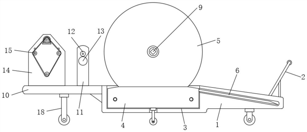
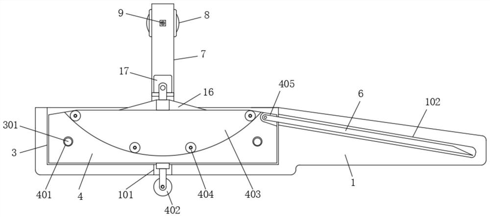
[0029] Example one, by Figure 1 to Figure 6Given, the present invention includes a base 1, a handle 2 is installed at one end of the top of the base 1, a groove 3 is installed at the other end of the top of the base 1, and a moving plate 4 is installed inside the groove 3. The moving plate 4 can be installed effectively. The top of the moving plate 4 is provided with a line roller 5, and one end of the moving plate 4 is installed with a rotating plate 6. Through the setting of the rotating plate 6, the line roller 5 can be easily moved from the moving plate 4. For assembly and disassembly, a first fixing plate 7 is installed on the top of the base 1, a first motor 8 is installed on the upper part of one side of the first fixing plate 7, and a rotating shaft 9 is installed at the output end of the first motor 8. The rotating shaft 9 and the line roller 5 One end of the base 1 is fixedly installed with a connecting plate 10, one side of the top of the connecting plate 10 is sym...

Embodiment 2

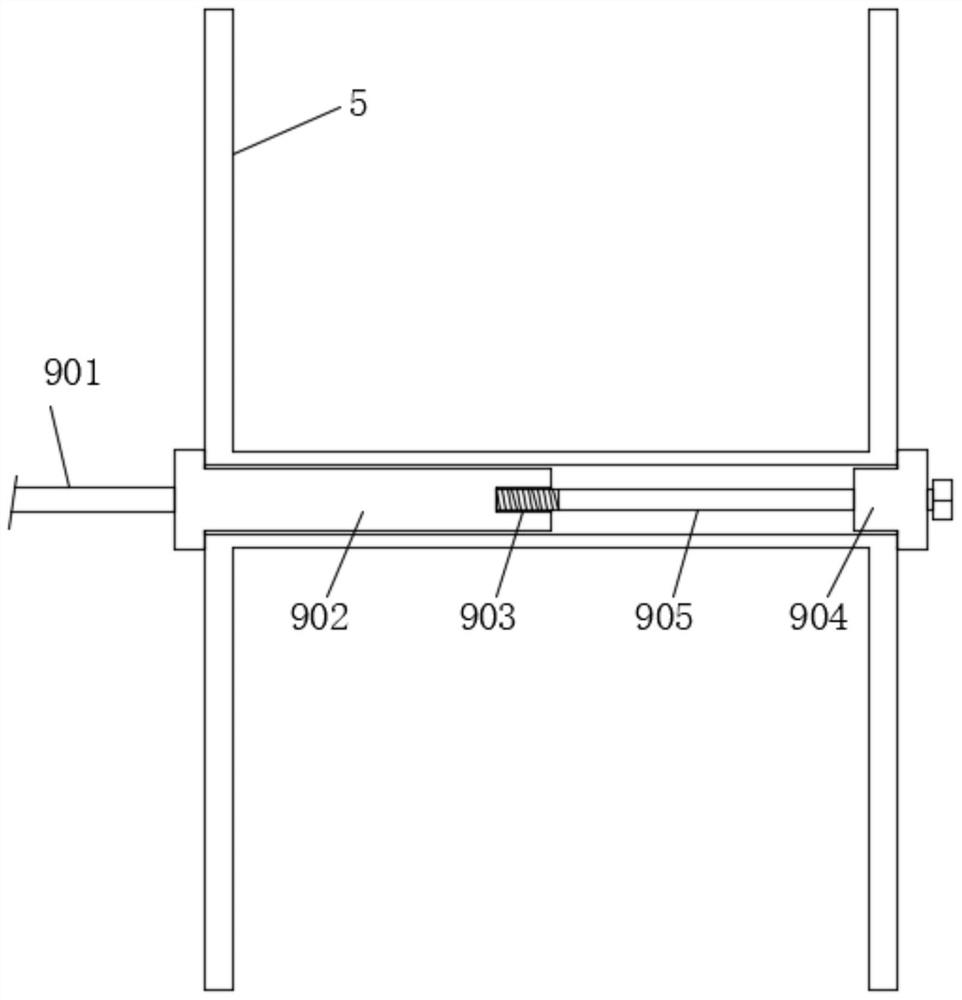
[0034] Embodiment 2, on the basis of Embodiment 1, by Figure 4 Given, the cable arrangement 12 includes a hollow sleeve 1201, an insertion rod 1202, a threading ring 1203, a disc 1204 and a tooth 1205. The hollow sleeve 1201 is movably plugged on the top of one of the second fixing plates 11, and the insertion rod 1202 It is installed on the top of the other second fixing plate 11, and the insertion rod 1202 is movably inserted into the hollow sleeve 1201. so that the cables can be arranged in an orderly manner.

Embodiment 3

[0035] Embodiment 3, on the basis of Embodiment 3, by Figure 4 Given, the cable power mechanism 13 includes a second motor 1301, a rotating rod 1302, a cylinder 1303 and a continuous cross slot 1304, the second motor 1301 is installed on the upper part of the other second fixing plate 11, and the rotating rod 1302 is rotatably installed Between the two second fixing plates 11 , a cylinder 1303 is installed at one end of the rotating rod 1302 , the other end of the rotating rod 1302 is connected to the output end of the second motor 1301 , and a continuous cross-through slot 1304 is opened at the end of the cylinder 1303 . On the surface, the bottom ends of the latching teeth 1205 are movably latched in the interior of the continuous intersecting through-grooves 1304 , so as to provide power to the cable arranging mechanism 12 .


PUM


Abstract

The invention relates to the technical field of cable processing equipment, and discloses a cable tensioning device, which solves the problem that the cable tensioning device cannot arrange the coiled cables, but coils in an orderly manner. The problem of not being able to easily and effectively install and disassemble the line roller and empty line roller with cables, which includes a base, one end of the top of the base is installed with a handle, the other end of the top of the base is installed with a groove, and the groove is A moving plate is installed inside, a wire roller is installed on the top of the moving plate, a rotating plate is installed at one end of the moving plate, a first fixing plate is installed on the top of the base, and a first motor is installed on the upper part of one side of the first fixing plate; this cable The wire tightening device can orderly wire the coiled cables, so that the coiled cables are more perfect and the coiling efficiency is better. It is convenient for workers to use and reduces the labor intensity of workers.

Description

technical field [0001] The invention belongs to the technical field of cable processing equipment, in particular to a cable tightening device. Background technique [0002] Cable is a general term for optical cables, cables and other items. There are many uses for cables. They are mainly used to control installation, connect equipment, and transmit power. It is a common and indispensable thing in daily life. Therefore, the installation requires special care. [0003] The patent application with the publication number CN210795289U discloses a tensioning device for a power pay-off cable for a power system. The cable tensioning device is composed of the following structures: a base; a support column; a servo motor; a plug-in rod; a sleeve rod; a bracket; Limit hole; sliding wheel; limit block; fixed rod; vertical plate; limit roller; mounting plate; cylinder; The cable is paid off and tightened, the support and the support column are driven by the cylinder, the support column...

Claims


Application Information

Patent Timeline
Patent Type & Authority Patents(China)
IPC IPC(8): B65H75/44B65H67/02B65H67/04
CPCB65H75/4486B65H75/4405B65H67/02B65H67/0411B65H67/0417B65H2701/32B65H2701/34
Inventor 蔡海多李海萍邱雪南叶向辉
Owner 江西泉新电气有限公司
Features
  • R&D
  • Intellectual Property
  • Life Sciences
  • Materials
  • Tech Scout
  • Unparalleled Data Quality
  • Higher Quality Content
  • 60% Fewer Hallucinations
Learn More