Plasma lamp structure of microwave illuminating apparatus

A technology for lighting devices and plasma lamps, which is applied in the field of ion lamps, and can solve the problems that the plane mirror cannot be fixed, placed, and reduces the stability and reliability of the equipment.

Inactive Publication Date: 2003-10-08
LG ELECTRONICS INC
View PDF0 Cites 0 Cited by
  • Summary
  • Abstract
  • Description
  • Claims
  • Application Information

AI Technical Summary

Problems solved by technology

[0019] However, in the existing microwave lighting device having the above-mentioned plasma lamp structure, since there is a gap (gap) between the protrusion of the microwave waveguide and the supporting plate of the resonant cavity where the plane mirror is placed, microwaves fill this gap, resulting in generation of spark problem
[0020] In addition, because of this gap, the plane mirror cannot be placed firmly and supported, reducing the stability and reliability of the device

Method used


Image

  • Plasma lamp structure of microwave illuminating apparatus
  • Plasma lamp structure of microwave illuminating apparatus
  • Plasma lamp structure of microwave illuminating apparatus

Examples


Embodiment Construction

[0032] The invention will now be described in detail with reference to its preferred embodiments, examples of which are shown in the accompanying drawings.

[0033] The structure of the plasma lamp of the microwave lighting device according to the present invention will now be described with reference to the accompanying drawings.

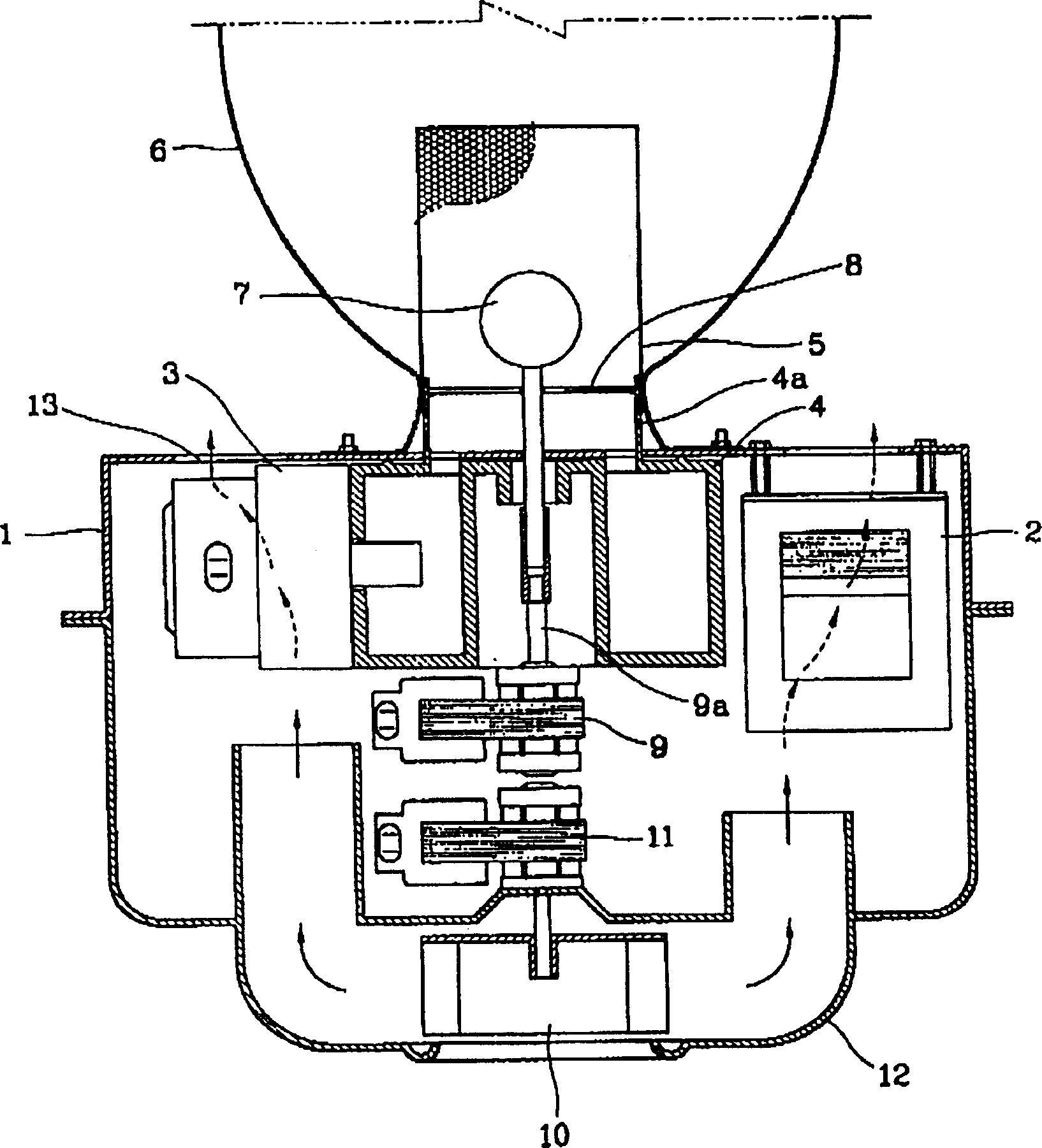
[0034] The rest of the microwave illuminating device of the present invention except the structure of the plasma lamp is the same as in the prior art, so their introduction is omitted here, and the same reference numerals are given to the same components in the prior art.

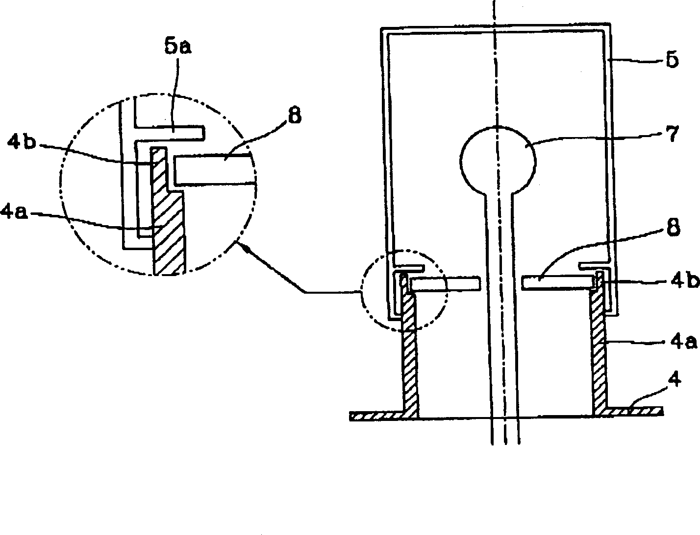
[0035] Figure 3A is a cross-sectional view showing the structure of the plasma lamp of the microwave lighting device according to the present invention, Figure 3B is a plan view showing the structure of the plasma lamp of the microwave lighting device according to the present invention.

[0036] As shown in the figure, the plasma lamp has a structure in which a plane mirror ...


PUM


Abstract

A plasma lamp structure of a microwave illumination apparatus including: mirror mounting portions formed to be concavo-convex at regular intervals so as to partially contact the bottom surface of a mirror in a supporting manner at the front end portion of a protrusion of a microwave guide in which microwave is guided toward a resonator; and support pieces formed to supportedly press the upper surface of the mirror mounted on the mirror mounting portion on the inner circumferential surface of the resonator that is extrapolated at the microwave guide. By having such structure, no space is allowed between the front end portion of the protrusion and the support pieces where the mirror is fixed, and a spark can be prevented from occurring and the mirror can be firmly supported.

Description

technical field [0001] The invention relates to a plasma lamp of a microwave lighting device, in particular to a structure of a plasma lamp of a microwave lighting device which can prevent sparks from being generated in the plasma lamp and ensure that a plane mirror is firmly placed in the lamp. Background technique [0002] At present, a microwave lighting device with an electrodeless bulb installed in a resonant cavity, which has a long duration and excellent lighting efficiency, has been greatly developed. [0003] figure 1 is a plan view of a common microwave lighting device according to the prior art. [0004] As shown in the figure, the microwave lighting device includes: a high-voltage generating unit 2, which is arranged on one side of the front side of a predetermined shape of the housing 1; a microwave generating unit 3, which is arranged on the other side of the front side of the housing 1, for Microwaves are generated from the high voltage generated by the high...

Claims


Application Information

Patent Timeline
IPC IPC(8): F21S2/00F21Y101/00H01J61/62H01J65/04H05B41/24
CPCH01J65/044H01J61/62
Inventor 姜亨周
Owner LG ELECTRONICS INC
Why Eureka
Try Eureka