High-frequency heating apparatus

a heating apparatus and high-frequency technology, applied in lighting and heating apparatus, electric/magnetic/electromagnetic heating, stoves or ranges, etc., can solve the problems of difficult application of scorching, small heating value, and small amount of absorbing high-frequency, so as to prevent scorching

Inactive Publication Date: 2005-03-10
PANASONIC CORP
View PDF6 Cites 11 Cited by
  • Summary
  • Abstract
  • Description
  • Claims
  • Application Information

AI Technical Summary

Benefits of technology

[0048] According to the thirty-third aspect of the invention, the high-frequency heating element and the saucer are fixed to and united with each other by the adhesive member, the high-frequency heating element made of ceramic is made longer than the saucer made of metal, and the high-frequency heating element is placed on the rails provided on the left and right side surfaces of the heating room. Hereby, the number of parts is reduced, and the simple constitution is provided.
[0049] According to the thirty-fourth aspect of the invention, the high-frequency heating element and the saucer are fixed to and united with each other by the adhesive member, the saucer made of metal has insulating members on its left and right sides in the depth direction of the heating room, and the insulating members are placed on the rails provided on the left and right side surfaces of the heating room. Hereby, since gaps can be provided into the heating room at the heat-cooking time, spark can be prevented.

Problems solved by technology

However, in the conventional constitution, since the metal surface is coated with the high-frequency heating element, for example, a microwave heating element, the heating element is close to the metal surface, so that the electric field in the vicinity of the heating element is weak, the amount of absorbing the high-frequency becomes small, and heating value becomes small, whereby there is a problem that the scorch is difficult to be applied.
Moreover, since the microwave supply port is positioned on the side wall in the conventional constitution, a portion of a high frequency heating element closer to the microwave supply port receives the microwave more strongly, so that there is a problem that unevenness in heating is produced in the high-frequency heating element.

Method used


Image

  • High-frequency heating apparatus
  • High-frequency heating apparatus
  • High-frequency heating apparatus

Examples


embodiment 1

[0073] (Embodiment 1)

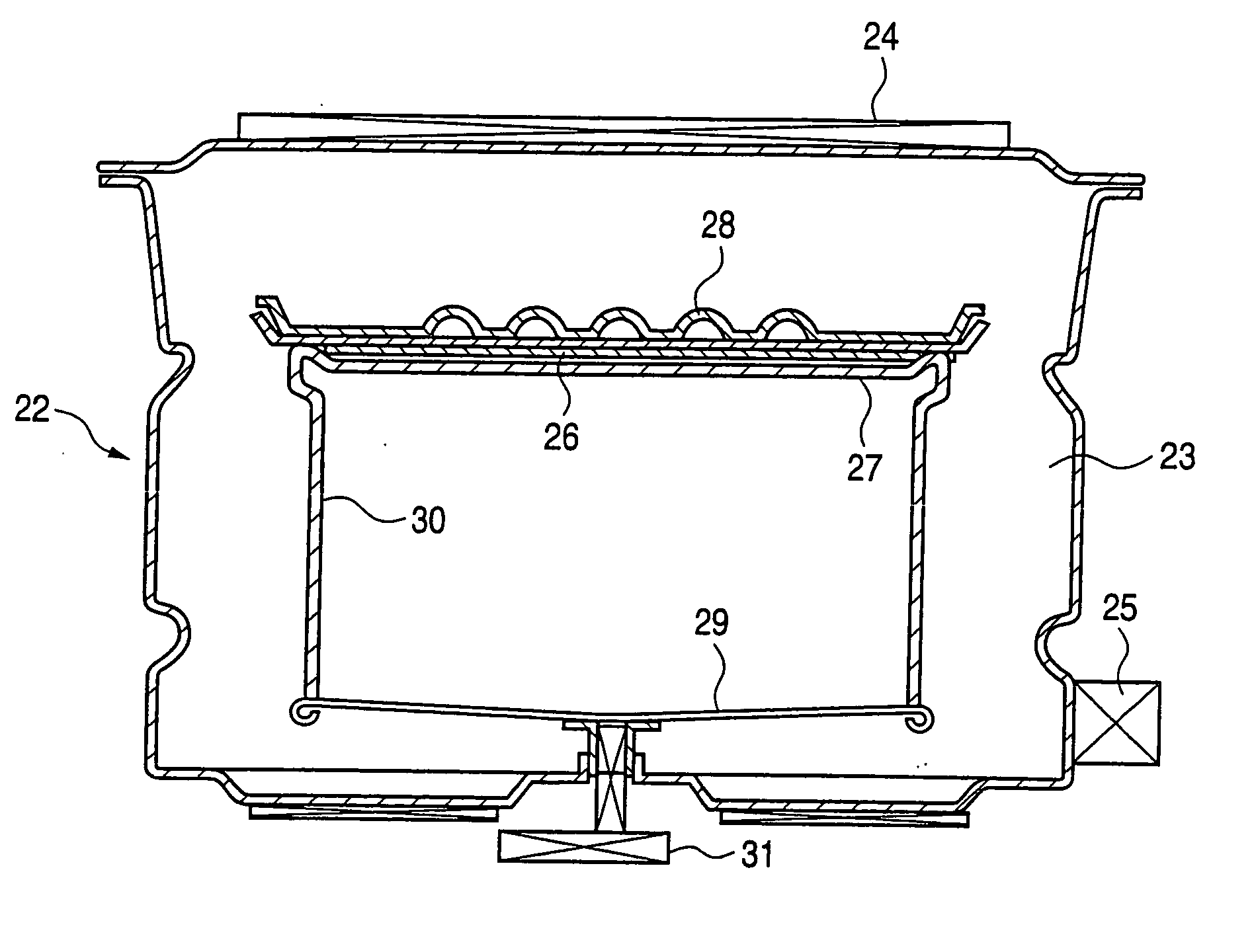
[0074]FIG. 1 is a schematic sectional view showing the constitution of a high-frequency heating apparatus of the invention.

[0075] A high-frequency heating apparatus 4 comprises a heating room 5 for storing therein a subject to be heated, a heating unit 6 that is provided in the heating room and performs heater heating, a high-frequency generating unit 7 that is provided at the bottom of the heating room and generates a high-frequency wave to perform high-frequency heating, a high-frequency heating element 9 having a high-frequency heat generating film 8 on its rear surface, and a saucer 10 for placing thereon the subject to be heated.

[0076] The high-frequency wave generated from the high-frequency generating unit 7 is uniformly supplied from the downside into the heating room 2 by a high-frequency dispersing unit 11. And, the saucer 10 is placed on rails 12 provided on side surfaces of the heating room to be used.

[0077] As the high-frequency heating element 9...

embodiment 2

[0101] (Embodiment 2)

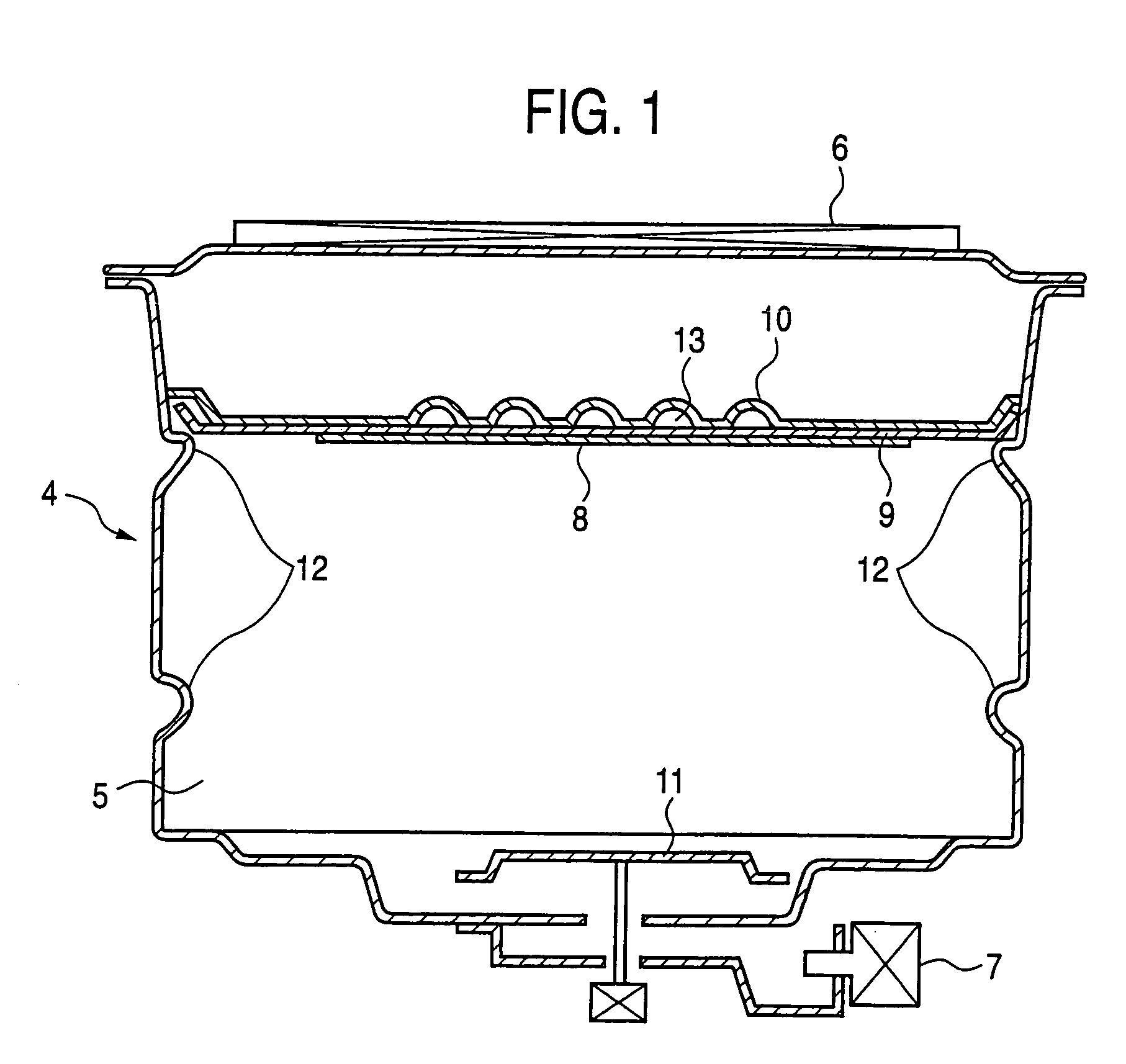
[0102]FIG. 2 is a sectional view showing the constitution of a main portion of a high-frequency heating apparatus according to a second embodiment.

[0103] In FIG. 2, a gap 17 is provided between a high-frequency heating element 15 having a high frequency heat generating film 14 and a saucer 16 made of metal. Other constitution of the high-frequency heating apparatus is similar to that in the first embodiment.

[0104] In case that chicken dark meat was heated under the above constitution, scorch could be applied onto the both sides of the meat. We think that this is due to the following reason: Since the distance between the high-frequency heat generating film 14 and the metal surface of the saucer 16 becomes large, the strength of electric field on the high-frequency heat generating film 14 becomes high, and heat generation in the high-frequency heat generating film 14 becomes high; and compared with a case where there is no gap, the amount of the high-frequency ...

embodiment 3

[0106] (Embodiment 3)

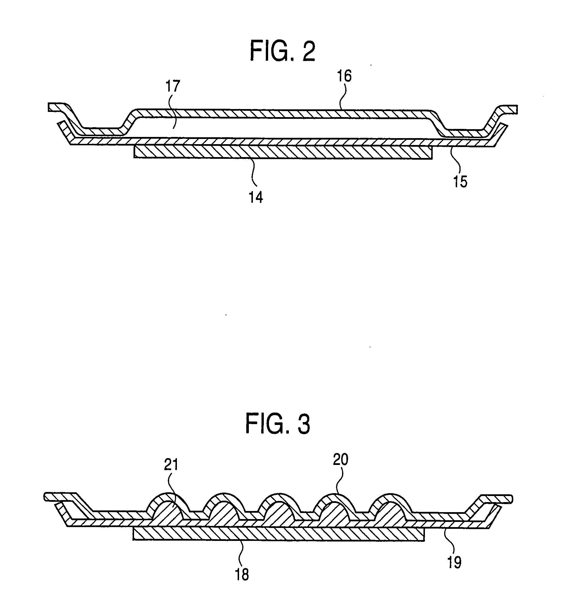
[0107]FIG. 3 is a sectional view showing the constitution of a main portion of a high-frequency heating apparatus according to a third embodiment.

[0108] In FIG. 3, a portion between a high-frequency heating element 19 having a high-frequency heat generating film 18 and a saucer 20 made of metal is filled with ceramic material that is dielectrics. However, gaps 21 corresponding to the gaps 13 in the first embodiment are provided to make a distance between the metal surface of the saucer 20 and the high-frequency heat generating film 18. Other constitution of the high-frequency heating apparatus is the same as that in the first embodiment.

[0109] In case that chicken dark meat was heated under the above constitution, the scorch could be applied onto the both sides of the meat. We think that this is due to the following reason: Since the distance between the high-frequency heat generating film 18 and the metal surface of the saucer 20 becomes large, the strength o...


PUM


Abstract

The present invention provides a high-frequency heating apparatus which can heat the inside of the subject to be heated by high-frequency heating, and can apply scorch onto the surface of the subject to be heated. The high-frequency heating apparatus comprises a heating room for storing therein a subject to be heated, a heating unit that is provided at the upper portion of the heating room and performs heater heating, a high-frequency generating unit that is provided at the bottom of the heating room and generates a high-frequency wave to perform high-frequency heating, a high-frequency heating element having a high-frequency heat generating film on its rear surface, and a saucer for placing thereon the subject to be heated, in which a gap is provided between the high-frequency heating element and the saucer. Hereby, scorch can be applied onto a surface of the subject to be heated.

Description

FIELD OF THE INVENTION [0001] The present invention relates to a high-frequency heating apparatus, which can heat the inside of an subject to be heated by high-frequency heating and apply scorch onto a surface of the subject to be heated. BACKGROUND ART [0002] Conventionally, as this type of high-frequency heating apparatus, there is, for example, an apparatus as disclosed in Japanese Patent Laid-Open No. 2562 / 1998. FIG. 13 is a front view showing a microwave oven 1 that is the above conventional high-frequency heating apparatus in perspective, which shows the constitution thereof. [0003] According to the above related art, a microwave generated from a magnetron that is the high-frequency generating apparatus is supplied form a microwave supply port 2 formed on a side wall surface into a heating room 3. [0004] Further, as a food table plate, a surface of a base made of metal such as iron is coated with a thin film-like microwave heating element. [0005] However, in the conventional c...

Claims


Application Information

Patent Timeline
Patent Type & Authority Applications(United States)
IPC IPC(8): A47J36/02A47J36/24H05B6/64H05B6/80
CPCA47J36/027A47J36/2483Y10S99/14H05B6/6408H05B6/6494H05B6/6402H05B6/64F24C7/02H05B6/80A47J36/02
Inventor ISOGAI, MAMORUYAMASAKI, TAKAHIKOSUEHIRO, MINEKOUCHIYAMA, SATOMIFUJISHITA, KAZUO
Owner PANASONIC CORP
Why Eureka
Try Eureka