Controllable battery charging circuit and charger

A battery charging and circuit technology, applied in battery circuit devices, current collectors, circuit devices, etc., can solve the problems of affecting battery life, increasing the overall power dissipation of the system, and the battery port voltage cannot reach the battery voltage. Reduce the effect of lowering and avoiding ignition

Inactive Publication Date: 2016-10-12
北京云迹科技股份有限公司
View PDF6 Cites 10 Cited by
  • Summary
  • Abstract
  • Description
  • Claims
  • Application Information

AI Technical Summary

Problems solved by technology

Due to the voltage drop of the diode, the battery terminal voltage cannot reach the full battery voltage and affect the life of the battery
In addition, this voltage drop reduces the efficiency of the power supply circuit and increases the overall power dissipation of the system

Method used


Image

  • Controllable battery charging circuit and charger
  • Controllable battery charging circuit and charger

Examples


Embodiment 1

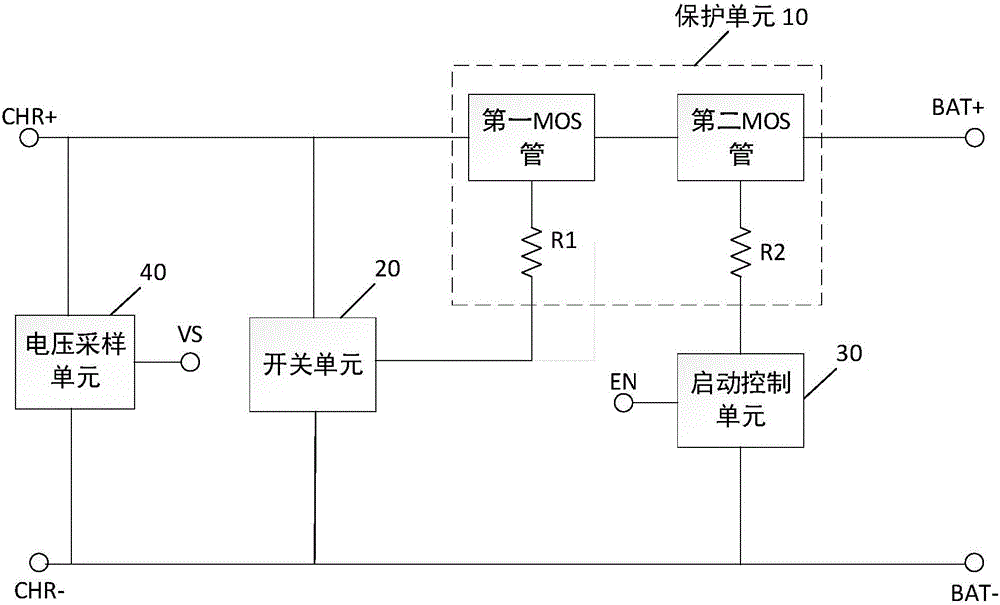
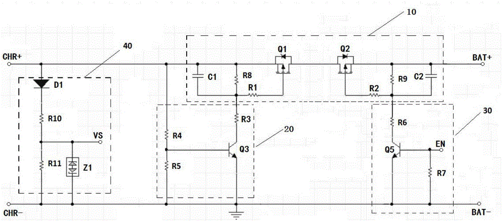
[0013] figure 1 A schematic diagram of a controllable battery charging circuit according to an embodiment of the present invention is shown.

[0014] In this embodiment, the controllable battery charging circuit according to the present invention may include: a protection unit 10 , a switch unit 20 , a start control unit 30 and a voltage sampling unit 40 . The protection unit 10 includes a first MOS transistor Q1, a second MOS transistor Q2, and resistors R1 and R2. The first MOS transistor Q1 and the second MOS transistor Q2 are connected in reverse, and connected in series between the positive electrode CHR+ of the circuit input and the positive electrode BAT+ of the circuit output. One end of the resistor R1 is connected to the gate of the first MOS transistor Q1, and the other end is used as the first control end of the protection unit 10; one end of the resistor R2 is connected to the gate of the second MOS transistor Q2, and the other end is used as the first control end...


PUM


Abstract

The invention discloses a controllable battery charging circuit and a charger. The circuit comprises a protection unit, a switch unit, a start-up control unit and a voltage sampling unit. The protection unit comprises a first MOS transistor, a second MOS transistor, a resistor R1 and a resistor R2. The first MOS transistor and the second MOS transistor are in reverse connection and are connected in series between the input positive pole and the output positive pole of a circuit. One end of the resistor R1 is connected with the grid electrode of the first MOS transistor, and the other end of the resistor R1 serves as the first control end of the protection unit. One end of the resistor R2 is connected with the grid electrode of the second MOS transistor, and the other end of the resistor R2 serves as the second control end of the protection unit. The switch unit controls the on / off state of the first MOS transistor. The start-up control unit controls the on / off state of the second MOS transistor. The voltage sampling unit samples the voltage of the charger. The two MOS transistors of the circuit are in reverse connection, so that the forward voltage drop generated by the circuit during the charging process is reduced. Therefore, the battery charging volume is improved and the system power consumption is reduced.

Description

technical field [0001] The present invention relates to a battery charging circuit, and more particularly, to a controllable battery charging circuit and a charger. Background technique [0002] Existing battery charging circuits and chargers usually use diodes to prevent reverse connection and backflow. Due to the voltage drop of the diode, the battery terminal voltage cannot reach the full battery voltage and affect the life of the battery. In addition, this voltage drop reduces the efficiency of the power supply circuit and increases the overall power dissipation of the system. Therefore, it is necessary to develop a battery charging circuit and a charger that can increase charging capacity and reduce system power consumption. [0003] The information disclosed in the Background of the Invention section is only intended to enhance the understanding of the general background of the present disclosure, and should not be considered as an acknowledgment or in any form to im...

Claims


Application Information

Patent Timeline
Patent Type & Authority Applications(China)
IPC IPC(8): H02J7/00
CPCH02J7/0034H02J7/0068
Inventor 韦志辉张和光
Owner 北京云迹科技股份有限公司
Why Eureka
Try Eureka