Swing type buffer energy consumption type bridge seismic resistance check block structure

An energy-consuming and swinging technology, applied in the direction of bridges, bridge parts, bridge construction, etc., can solve the problem of large manpower and material resources for strengthening or rebuilding bridges, insufficient horizontal shear force of reinforced concrete blocks, and damage to beams and concrete blocks. and other problems, to achieve the effect of buffering and consuming seismic energy, preventing vertical collision damage, and reducing local damage

Pending Publication Date: 2021-02-23
NANCHANG UNIV
View PDF0 Cites 0 Cited by
  • Summary
  • Abstract
  • Description
  • Claims
  • Application Information

AI Technical Summary

Problems solved by technology

[0004] The collapse of bridges in earthquakes will bring many hazards, and there are still many bridges designed according to the original design standards in my country, or bridges that have been damaged to a certain extent. They cannot meet the social needs of today's large number of vehicles and heavy transportation weight. Renovating these bridges requires a lot of manpower and material resources
[0005] In order to limit the large displacement of the upper girder of the bridge in the transverse bridge direction, reinforced concrete stoppers are often installed on both sides of the top of the pier cover girder, but the collision between the ordinary reinforced concrete stopper and the girder is a rigid collision, and the impact force is very large. Large, it is easy to cause local damage to the beam body and the concrete block, and the horizontal shear force of the reinforced concrete block is usually insufficient in the earthquake, the block is prone to irreparable damage, and cannot well limit the displacement of the beam body

Method used


Image

  • Swing type buffer energy consumption type bridge seismic resistance check block structure
  • Swing type buffer energy consumption type bridge seismic resistance check block structure
  • Swing type buffer energy consumption type bridge seismic resistance check block structure

Examples


Embodiment Construction

[0030] Below the present invention is further described:

[0031] see Figure 1-7 .

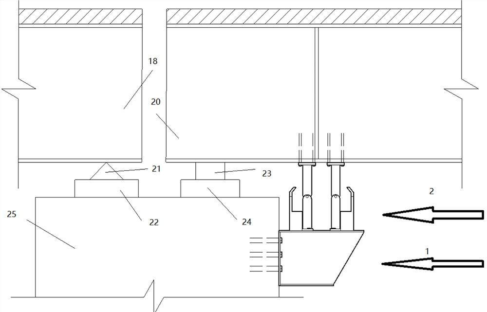
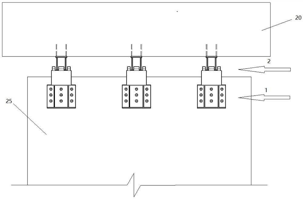
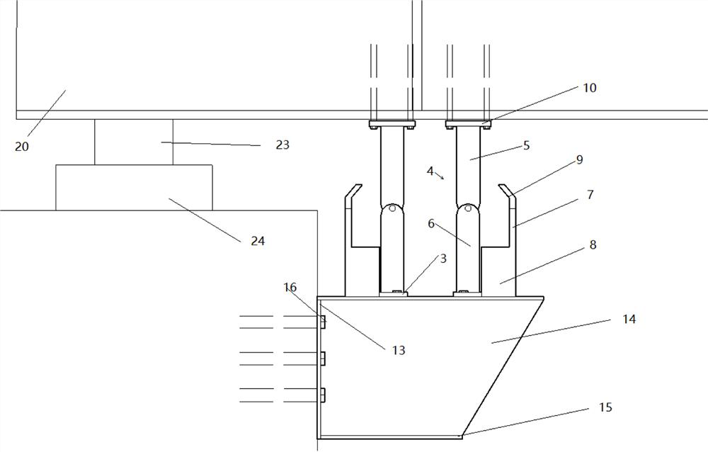
[0032] The invention discloses an anti-seismic block structure of a swinging buffer energy-dissipating bridge, which comprises a steel corbel 1 and a block structure 2, and the steel corbel 1 is fixed near a movable support 23 by steel corbel side plate bolts 16 Above the side wall of the bridge pier 25, the block structure 2 is fixed on the top of the steel corbel 1 by bolts, and fixed on the bottom of the main girder 18 or the second main girder 20 through the fixed steel plate 10 connected with the swing bar 4; The block structure 2 includes a steel base plate 3 , an energy-dissipating low-yield-point steel plate, a limit block 9 , a swing bar 4 and a fixed steel plate 10 .

[0033] The steel corbel 1 is arranged on the side of the top of the pier 25, which not only can increase the installation space of the block structure 2 for installation and construction, but also adjusts the vertic...


PUM


Abstract

The invention belongs to the technical field of bridge seismic resistance, and particularly relates to a swing type buffer energy consumption type bridge seismic resistance check block structure whichcomprises a steel corbel and a check block structure, the steel corbel is fixed to the side face of the top of a pier near a movable support, and the check block structure is fixed to the top of thesteel corbel, and comprises a steel bottom plate, an energy consumption type low-yield-point steel plate, a limiting block, a swing rod and a fixed steel plate. The bridge seismic resistance check block structure can effectively limit large displacement between the beam body and the bridge pier, prevent the beam body from falling in the bridge direction and the transverse bridge direction and being vertically separated from the supports, reduce damage to the movable supports and the expansion joints, meanwhile, the seismic resistance check block structure is arranged near each movable support,collision positions are scattered, the number of collision positions is large, and the earthquake force acting on each stop block structure can be effectively reduced. The check block body comprisesthe energy consumption type low-yield-point steel plate, and part of earthquake energy is consumed through plastic deformation.

Description

technical field [0001] The invention belongs to the field of anti-seismic technology of bridges, and in particular relates to a structure and an arrangement method of an anti-seismic block of a swing-type buffering energy-dissipating bridge for bridges. Background technique [0002] In order to improve the transportation efficiency of highways, protect the ecological environment along the highways, and save land resources, the idea of ​​replacing roads with bridges will lead the future infrastructure construction. However, my country is located between multiple seismic zones, and it is also a country with frequent earthquakes. When the earthquake comes, first of all, the safety of people's lives and property is threatened. On the other hand, the earthquake has caused serious damage to the bridge engineering in the earthquake area, cutting off the external traffic of the earthquake-stricken area, causing an island effect, and causing serious damage to the people after the ear...

Claims


Application Information

Patent Timeline
IPC IPC(8): E01D19/00
CPCE01D19/00
Inventor 田钦刘康霍振坤胡振秋
Owner NANCHANG UNIV
Why Eureka
Try Eureka