Energy dissipation buffer type limitable bridge anti-seismic check block structure with steel spring

A technology of steel spring and block structure, which is applied in the direction of bridges, bridge parts, bridge construction, etc., and can solve the problems of large manpower and material resources in strengthening or rebuilding bridges, insufficient horizontal shear force of reinforced concrete blocks, damage to beam bodies and concrete blocks, etc. problem, achieve the effect of buffering and consuming seismic energy, simple structure, and preventing vertical collision damage

Pending Publication Date: 2020-11-13
NANCHANG UNIV
View PDF0 Cites 0 Cited by
  • Summary
  • Abstract
  • Description
  • Claims
  • Application Information

AI Technical Summary

Problems solved by technology

[0006] The collapse of bridges in earthquakes will bring many hazards, and there are still many bridges designed according to the original design standards in my country, or bridges that have been damaged to a certain extent. They cannot meet the social needs of today's large number of vehicles and heavy transportation weight. Renovating these bridges requires a lot of manpower and material resources
[0007] In order to limit the large displacement of the upper girder of the bridge in the transverse bridge direction, reinforced concrete stoppers are often installed on both sides of the top of the pier cover girder, but the collision between the ordinary reinforced concrete stopper and the girder is a rigid collision, and the impact force is very large. Large, it is easy to cause local damage to the beam body and the concrete block, and the horizontal shear force of the reinforced concrete block is usually insufficient in the earthquake, the block is prone to irreparable damage, and cannot well limit the displacement of the beam body

Method used


Image

  • Energy dissipation buffer type limitable bridge anti-seismic check block structure with steel spring
  • Energy dissipation buffer type limitable bridge anti-seismic check block structure with steel spring
  • Energy dissipation buffer type limitable bridge anti-seismic check block structure with steel spring

Examples


Embodiment Construction

[0030] Below the present invention is further described:

[0031] see Figure 1-6 .

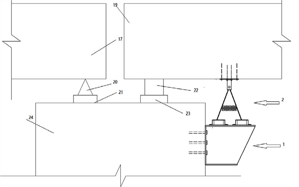
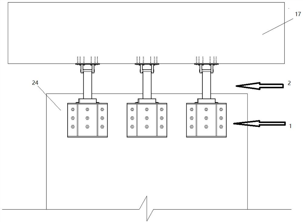
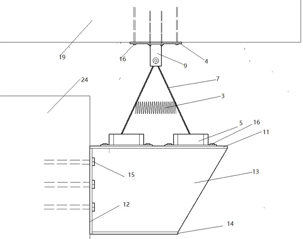
[0032] The invention discloses an energy-dissipating buffer type limitable bridge anti-seismic block structure with steel springs, comprising a steel corbel 1 and a block structure 2, the steel corbel 1 is fixed on the steel corbel side plate bolt 15 The side of the top of the bridge pier 24 near the movable support, the bottom of the stopper structure 2 is fixed on the top of the steel corbel 1 by bolts 16, and the top of the stopper structure 2 is fixed on the bottom of the main girder of the bridge by the fixing plate bolts 16, The block structure 2 is composed of a steel plate 7, a steel spring 3, a hinge structure 8, a roller 6, a hinge fixed body 9 and a stopper 5 with four round holes.

[0033] The steel corbel 1 is arranged on the side of the top of the pier 24, which not only can increase the installation space of the block structure 2 for installation and construction, but also ca...


PUM


Abstract

The invention belongs to the technical field of bridge earthquake resistance, and particularly relates to an energy dissipation buffer type limitable bridge anti-seismic check block structure with a steel spring. The structurecomprises a steel corbel and a check block structure, the steel corbel is fixed to the side face of the top of a pier near a movable support, and a check block body is fixedto the top of the steel corbel and comprises a steel plate, a steel spring, a hinge structure, a rolling shaft, a hinge fixing body and a four-round-hole limiting stopper. By means of the bridge anti-seismic check block structure, large displacement between the beam body and the bridge pier can be effectively limited, beam falling damage of the beam body in the bridge direction and the transversebridge direction and damage that the beam body is vertically separated from the support are prevented, damage to the movable support and the expansion joint is reduced, and seismic energy can be consumed by means of movement of the rolling shafts. The device is simple in structure and convenient to construct.

Description

technical field [0001] The invention belongs to the field of anti-seismic technology of bridges, and in particular relates to an energy-dissipating buffer type limitable bridge anti-seismic block structure with steel springs. Background technique [0002] With the development of my country's economic strength, the investment in transportation construction is also increasing. The construction of large-scale transportation infrastructure has promoted the development of urban and regional economies. In order to save land resources, my country's transportation construction advocates the use of bridges instead of roads, which also brings opportunities for the rapid development of bridge engineering in my country. Now more and more high-speed railways, viaducts, and long-span bridges have been built. There are more than one million bridges built or under construction in my country. [0003] my country is located among many earthquake zones, and it is also a country with frequent ...

Claims


Application Information

Patent Timeline
Patent Type & Authority Applications(China)
IPC IPC(8): E01D19/00E01D19/02
CPCE01D19/00E01D19/02
Inventor 田钦刘康李顺治樊霖涛
Owner NANCHANG UNIV
Why Eureka
Try Eureka