Plate safe separation method and power charging structure

A separation method and plate technology, applied in the field of explosion processing, can solve problems such as machine crash and death, and achieve the effects of reducing the number of experiments, reducing local damage, and slowing the release of explosive energy.

Inactive Publication Date: 2018-11-23
ANHUI UNIV OF SCI & TECH
View PDF7 Cites 1 Cited by
  • Summary
  • Abstract
  • Description
  • Claims
  • Application Information

AI Technical Summary

Problems solved by technology

[0002] Aircraft engine non-containment accidents can lead to serious air accidents

Method used


Image

  • Plate safe separation method and power charging structure
  • Plate safe separation method and power charging structure
  • Plate safe separation method and power charging structure

Examples


Embodiment 1

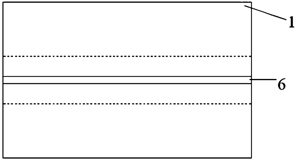
[0025] refer to figure 1 , the plate 1 is a titanium alloy plate with a length of 120 mm, a width of 66 mm, and a height of 12 mm.

[0026] refer to figure 2 , The two sides of the central axis of the plate 1 are respectively marked with grooves 6 with a length of 120 mm, a width of 0.5 mm and a depth of 1 mm.

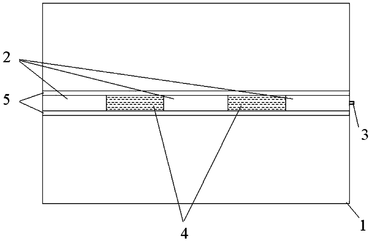
[0027] Drill a circular hole with a diameter of 8 mm and a length of 120 mm at the center of the plate 1, and the minimum wall thickness of the plate 1 is 2 mm at this time. The buffer layer 5 is a PVC pipe with a length of 120 mm and a thickness of 1.5 mm. The buffer layer 5 is put into the central circular hole of the plate 1 . Dynamite 2 is 25mm long. The spacer layer 4 has a length of 20mm, and the spacer layer 4 is a structure formed by covering the nonel with a plastic sleeve. The spacer layer 4 is placed between the explosives 2; the explosives 2 are detonated by the detonator 3.

[0028] According to the above-mentioned embodiment, the explosive 2 is deton...

Embodiment 2

[0031] When the length of the spacer layer 4 is 0, the charge structure in the hole of the plate 1 is a continuous charge structure, which is similar to the first embodiment and will not be repeated here.


PUM


Abstract

The invention relates to a plate safe separation method and a powder charging structure. The method utilizes theoretical derivation to reduce the main control parameters in the separation process of aplate. The power charging structure comprises the plate, an explosive, a detonator, a buffer layer, a spacer layer and a groove. The structure is characterized in that: a circle hole is arranged in the center of the plate, the two sides of the central axis of the plate are provided with grooves, the buffer layer is arranged in the circle hole, the explosive is arranged in the buffer layer, and the spacer layer composed of wrapping a detonating tube with a plastic sleeve is arranged between the explosive, and the explosive is detonated by the detonator. According to the invention, the plate can be safely separated without redundant power, and a reliable theoretical derivation is provided; the experimental process is simple; and the required experiment quantity is small.

Description

technical field [0001] The invention relates to the field of explosive processing, in particular to a method for safely separating plates and a charging structure. Background technique [0002] Uncontained accidents of aeroengines can lead to serious air accidents involving aircraft crashes and fatalities. The high-speed and high-energy dangerous fragments fly out through the casing, which will damage the aircraft's cabin, fuel tank, hydraulic pipeline and electrical control circuit, etc., seriously endangering flight safety. Therefore, it is of great significance to study the inclusiveness of the aero-engine casing. The case containment test is a test to verify the containment capacity of the case for the blades that fly out after being broken. During the case containment test, the blades are required to break at a specific position and speed without excessive residual speed and fragments splashing. Now it is decided to use the explosion method to achieve the purpose of bl...

Claims


Application Information

Patent Timeline
Patent Type & Authority Applications(China)
IPC IPC(8): F42D3/00
Inventor 张书平王志富王猛马刘博
Owner ANHUI UNIV OF SCI & TECH
Why Eureka
Try Eureka