Collision sliding energy dissipation type bridge anti-seismic stop block structure with steel springs

An energy-consuming, steel spring technology, applied in bridges, bridge parts, bridge construction, etc., can solve problems such as large impact force, beam body and concrete block damage, and insufficient horizontal shear force of reinforced concrete block

Pending Publication Date: 2021-05-14
NANCHANG UNIV
View PDF0 Cites 0 Cited by
  • Summary
  • Abstract
  • Description
  • Claims
  • Application Information

AI Technical Summary

Problems solved by technology

[0004] In order to limit the large displacement of the upper girder of the bridge along the direction of the bridge, reinforced concrete stoppers are often installed on both sides of the top of the pier cover beam, but the collision between the ordinary reinforced concrete stopper and the girder is a rigid collision, and the impact force is very large. Cause local damage to the beam body and the concrete block, and the horizontal shear force of the reinforced concrete block in the earthquake is usually insufficient, the block is prone to irreparable damage, and cannot well limit the displacement of the beam body

Method used


Image

  • Collision sliding energy dissipation type bridge anti-seismic stop block structure with steel springs
  • Collision sliding energy dissipation type bridge anti-seismic stop block structure with steel springs
  • Collision sliding energy dissipation type bridge anti-seismic stop block structure with steel springs

Examples


Embodiment Construction

[0027] Below the present invention is further described:

[0028] see Figure 1-7 .

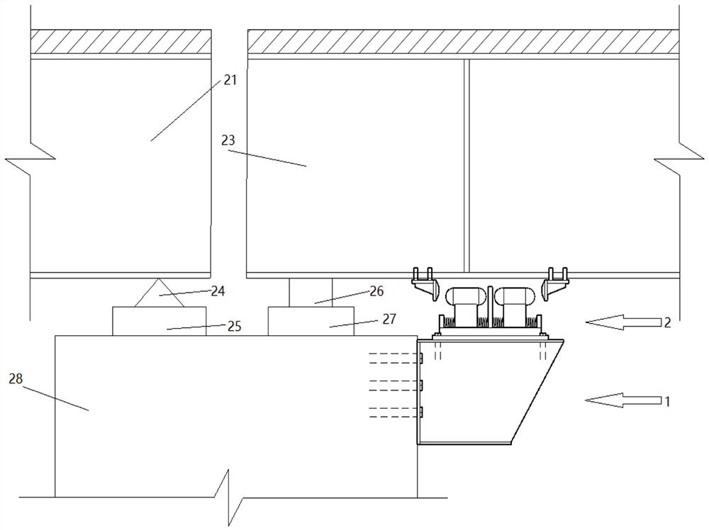
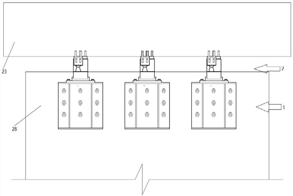
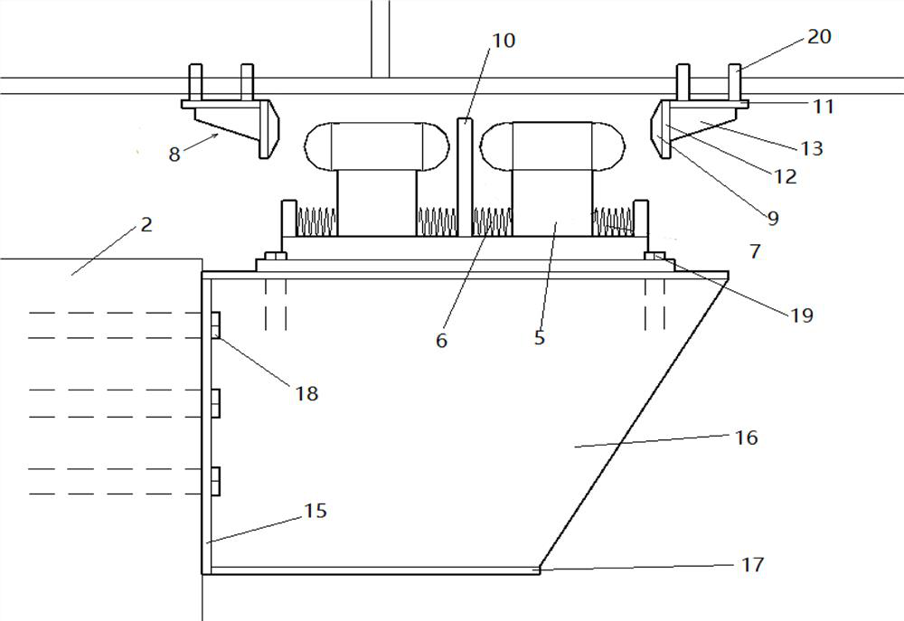
[0029] The invention discloses an anti-seismic block structure of a collision-sliding energy-dissipating bridge with steel springs, comprising a steel corbel 1 and a block structure 2, the steel corbel 1 is fixed on a bridge pier 28 through steel corbel side plate bolts 18 Above the side wall; the block structure 2 includes a steel base plate 3, a sliding groove 4, a collision block 8, an energy dissipation type low yield point steel plate 10 and a double hemispherical slider 5, and the steel base plate 3 is fixed by bolts 19 On the top of the steel corbel 1, the sliding groove 4 is welded on the top surface of the steel bottom plate 3, and an energy-dissipating low-yield point steel plate 10 is fixed in the middle, and steel baffles are welded on the left and right sides, A chute for the sliding of the double hemispherical slider 5 is formed between the energy dissipation type low yield po...


PUM


Abstract

The invention belongs to the technical field of bridge seismic resistance, and particularly relates to a collision sliding energy dissipation type bridge seismic resistance stop block structure with a steel spring, the collision sliding energy dissipation type bridge seismic resistance stop block structure comprises a steel corbel and a stop block structure, the steel corbel is fixed on the side face of the top of a pier close to a movable support, and the stop block structure is fixed on the top of the steel corbel and the bottom of a main beam. The stop block structure comprises a steel bottom plate, a sliding groove, a steel spring, a collision block, an energy dissipation type low-yield-point steel plate and a double-hemisphere sliding block. Earthquake energy is dissipated through collision, sliding and plastic deformation of the energy dissipation type low-yield-point steel plate, large displacement between a beam body and a bridge pier can be effectively limited, the beam body is prevented from falling down in the bridge direction, damage to a movable support and an expansion joint is reduced. Meanwhile, the anti-seismic stop block structure is arranged near each movable support, the collision positions are dispersed, the number of the collision positions is large, and the seismic force acting on each stop block structure can be effectively reduced.

Description

technical field [0001] The invention belongs to the field of anti-seismic technology of bridges, and in particular relates to an anti-seismic block structure and arrangement method of a collision-sliding energy-dissipating bridge with steel springs. Background technique [0002] In order to improve the transportation efficiency of highways, protect the ecological environment along the highways, and save land resources, the idea of ​​replacing roads with bridges will lead the future infrastructure construction. When the earthquake comes, first of all, the safety of people's lives and property is threatened. On the other hand, the earthquake has caused serious damage to the bridge engineering in the earthquake area, cutting off the external traffic of the earthquake-stricken area, causing an island effect, and causing serious damage to the people after the earthquake. The disaster relief work caused great difficulties, which led to subsequent secondary disasters, and the indir...

Claims


Application Information

Patent Timeline
IPC IPC(8): E01D19/00E01D19/06E01D19/02E01D19/04F16F15/08
CPCE01D19/00E01D19/02E01D19/04E01D19/06F16F15/08
Inventor 田钦刘康陈小钢叶小杭
Owner NANCHANG UNIV
Why Eureka
Try Eureka