Integrated television background wall structure with integrated wireless digital set top box
A technology for digital set-top boxes and background walls, applied in the field of background walls, can solve the problems of insufficient functionality, single structure, insufficient integration of wireless digital set-top boxes, etc. Effect
- Summary
- Abstract
- Description
- Claims
- Application Information
AI Technical Summary
Problems solved by technology
Method used
Image

Examples
Embodiment 1
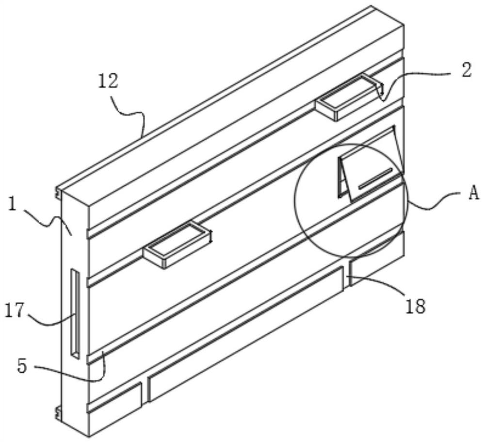
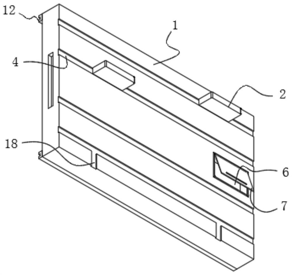
[0032] Please refer to Figure 1-5As shown, the present invention is an integrated TV background wall structure with an integrated wireless digital set-top box, including a background wall 1 and a mounting plate 13, and the mounting plate 13 is installed on the surface of the background wall 1, and the background wall 1 is fixedly installed. To enhance stability, the other surface of the background wall 1 is equipped with a storage board 2 to expand the storage space and enhance the practicality. One side of the storage board 2 is connected with a slider 3, and the side surface of the background wall 1 is provided with a chute 4. The slider 3 and The chute 4 is compatible, and the slider 3 is slidably matched with the chute 4, which facilitates the disassembly and lateral movement of the storage board 2, and enhances the adaptability and controllability of use. The side surface of the background wall 1 is also provided with a set-top box placement slot 6. It is convenient to p...
Embodiment 2
[0034] Wherein, background wall 1 surface is provided with decoration groove 5, and decoration groove 5 is positioned at the bottom of chute 4, is convenient to carry out the installation of decoration board, and cover plate 7 surface is provided with signal transceiver port 9, signal transceiver port 9 and set-top box placement groove 6 phases. Adaptation, which is conducive to the sending and receiving of signals, and the stability is stronger;
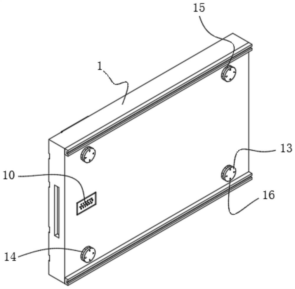
[0035] Wherein, background wall 1 rear end surface is connected with ventilating board 10, and ventilating board 10 is adapted to set-top box placement groove 6, strengthens the ventilating heat dissipation effect that set-top box uses, and background wall 1 rear end surface is connected with supporting block 12, carries out background wall 1 support protection;
[0036] Wherein, the rear end surface of the background wall 1 is provided with a recovery groove 15, the installation plate 13 is compatible with the recovery groove 15, a...
Embodiment 3
[0040] Please refer to Figure 1-5 As shown, a mounting plate 13 is installed on one surface of the background wall 1, and mounting screw holes 16 are provided on the surface of the mounting plate 13 to connect the mounting plate 13. The mounting plate 13 can be buckled on one side of the background wall 1. For convenience and stronger operation adaptability, a storage board 2 is installed on the other surface of the background wall 1, a slider 3 is connected to one side of the storage board 2, a chute 4 is provided on the side surface of the background wall 1, and the slider 3 and the chute 4 Compatible, and the sliding block 3 and the chute 4 are slidably matched to facilitate the disassembly and lateral movement of the storage board 2. The spacer teeth are also connected between the matching structure of the slider 3 and the chute 4 to limit the storage board 2. The position is fixed, and the set-top box placement slot 6 is also provided on the side surface of the backgroun...
PUM
 Abstract
Description
Claims
Application Information
PatSnap Eureka turns technology decisions into work you can execute. Powered by our Innovation Knowledge Graph, it runs expert workflows across engineering, life sciences, materials and intellectual property. Get your review-ready output in minutes.


