Waste gas sampling monitoring device in factory environment

A monitoring device and exhaust gas technology, which is applied in the direction of measuring devices, analyzing gas mixtures, and the structural details of gas analyzers. The effect of practicality

Inactive Publication Date: 2021-02-23
HENAN INST OF ENG
View PDF12 Cites 2 Cited by
  • Summary
  • Abstract
  • Description
  • Claims
  • Application Information

AI Technical Summary

Problems solved by technology

[0004] The purpose of the present invention is to provide an exhaust gas sampling and monitoring device in the factory environment to solve the problem that the existing exhaust gas sampling and monitoring device does not have the lifting function and the rotating function, and it will be incapable of dealing with the complex environmental exhaust gas, and the existing equipment can be moved. But it does not have the function of braking and stopping, and the problem of poor practicability on steep slopes

Method used


Image

  • Waste gas sampling monitoring device in factory environment
  • Waste gas sampling monitoring device in factory environment
  • Waste gas sampling monitoring device in factory environment

Examples


Embodiment 1

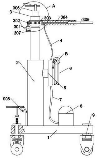
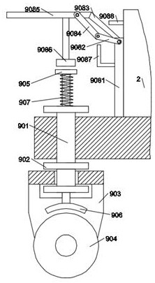
[0023] Such as figure 1 and figure 2 As shown, in the embodiment of the present invention, an exhaust gas sampling and monitoring device in a factory environment includes an installation base plate 1 on which a first telescopic rod 2 is fixed, and the upper end of the first telescopic rod 2 is connected to an exhaust gas A detection module 3, the exhaust gas detection module 3 is connected with a first wire 4, the first wire 4 is connected with a control cabinet 5, the upper end of the control cabinet 5 is connected with a stretching device 6, and the stretching device 6 and the control cabinet 5 Both are fixed on the lower half of the first telescopic rod 2, and the control cabinet 5 is also connected with a second wire 7, and the second wire 7 is connected with an alarm flashing light 8, and the alarm flashing light 8 is fixed on the first telescopic rod 2 On the installation base plate 1 on the right side, the lower ends of the four corners of the installation base plate ...

Embodiment 2

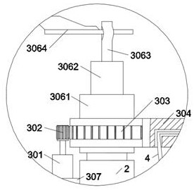
[0026] Such as figure 1 and figure 2 As shown, in the embodiment of the present invention, the exhaust gas detection module 3 includes a motor 301, the motor 301 is fixed on the bracket 307 at the upper end of the first telescopic rod 2, the motor 301 is connected with a gear 302, and the gear 302 The incomplete gear 303 is meshed, the toothless end of the incomplete gear 303 is connected with a long rod 304, and the end of the long rod 304 is connected with a high-precision thermal probe 305, which is located at the lower end of the incomplete gear 303 and is connected to the At the end of the first telescopic rod 2, a wind vane 306 is connected to the upper end of the incomplete gear 303.

[0027] In the embodiment of the present invention, the high-precision thermal probe 305 generates an electromotive force with the change of the exhaust gas, and the electromotive force generates a current that is transmitted to the control cabinet 5 through the first wire 4; the rotatio...

Embodiment 3

[0029] Such as figure 1 and figure 2 As shown, in the embodiment of the present invention, the wind vane 306 includes a base 3061, a cylindrical boss 3062 is fixed on the upper end of the base 3061, and a rotating column 3063 is rotatably connected to the cylindrical boss 3062, and the rotating column The upper end of 3063 is horizontally connected with weathervane 3064.

[0030] In the embodiment of the present invention, the wind vane 3064 is affected by the wind to change its direction, the cylindrical boss 3062 and the rotating column 3063 rotate relatively, and the wind vane 3064 is driven by the wind to rotate the rotating column 3063 .


PUM


Abstract

The invention relates to the technical field of factory environment waste gas sampling and monitoring, in particular to a waste gas sampling monitoring device in a factory environment.The device comprises a mounting bottom plate, a first telescopic rod is fixed to the mounting bottom plate, a waste gas detection module is connected to the upper end of the first telescopic rod, a first wire is connected to the waste gas detection module, the first wire is connected with a control cabinet, the upper end of the control cabinet is connected with a display screen, the display screen and the controlcabinet are both fixed to the lower half section of the first telescopic rod, the control cabinet is further connected with a second wire, the second wire is connected with an alarm flashing lamp, the alarm flashing lamp is fixed to the portion, on the right side of the first telescopic rod, of the mounting bottom plate, and steering devices are connected to the lower ends of the four corners ofthe mounting bottom plate. According to the device, the lifting and rotating functions are added on the basis of existing equipment, the application range of the device is wider, meanwhile, the steering devices with a braking function are designed, and the problem about practicability of a slope section is effectively solved.

Description

technical field [0001] The invention relates to the technical field of waste gas sampling and monitoring in factory environments, in particular to a device for sampling and monitoring waste gas in factory environments. Background technique [0002] In the factory, exhaust gas sampling and monitoring equipment is used in many places. For example, in places with high requirements for indoor exhaust gas sampling and monitoring, it is necessary to ensure that there are sufficient exhaust gas sampling and monitoring equipment to ensure that the exhaust gas in the production environment is within a controllable range. [0003] Existing exhaust gas sampling and monitoring devices do not have the functions of lifting and turning, and are unable to cope with the complex environment of exhaust gas. In addition, although the existing equipment can be moved, it does not have the function of braking and stopping, so it is not practical on steep slopes. Contents of the invention [0004...

Claims


Application Information

Patent Timeline
Patent Type & Authority Applications(China)
IPC IPC(8): G01N33/00
CPCG01N33/0009G01N33/0063
Inventor 周继军何新生孙震宇张俊伟秦昌郭忠杰付誉雷豪
Owner HENAN INST OF ENG
Why Eureka
Try Eureka