Movable wireless charging system and method, and electronic equipment

A technology for mobile wireless and charging equipment, applied in battery circuit devices, current collectors, electric vehicles, etc., can solve the problems of terminal products that are not suitable for mobile scenarios, short transmission distance, etc., to avoid the reduction of battery life and enlarge the opposite effect of distance

Pending Publication Date: 2021-02-23
上海影创信息科技有限公司
View PDF1 Cites 0 Cited by
  • Summary
  • Abstract
  • Description
  • Claims
  • Application Information

AI Technical Summary

Problems solved by technology

However, the transmission distance of traditional wireless charging technology is short, usually at the centimeter level, and the device to be charged needs to be visited at a specific location, which is not suitable for terminal products in mobile scenarios

Method used


Image

  • Movable wireless charging system and method, and electronic equipment
  • Movable wireless charging system and method, and electronic equipment
  • Movable wireless charging system and method, and electronic equipment

Examples


Embodiment 1

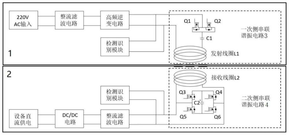
[0040] Such as figure 2 As shown, a mobile wireless charging system provided in this embodiment includes: a transmitting module 1 and a receiving module 2 .

[0041] The transmitting module 1 includes a first rectification and filtering circuit, a high-frequency inverter circuit, a first detection and identification module and a primary side series resonant circuit.

[0042] The first rectifying and filtering circuit rectifies and filters the input alternating current into direct current, and then outputs high-frequency alternating current to the primary side series resonant circuit after passing through the high-frequency inverter circuit.

[0043]The primary side series resonant circuit includes: MOS transistor Q1, MOS transistor Q2, capacitor C1 and transmitting coil L1, the drain of MOS transistor Q1 is connected to the source of MOS transistor Q2, and the source of MOS transistor Q1 is common to the drain of MOS transistor Q2 Connect one end of the capacitor C1, the oth...

Embodiment 2

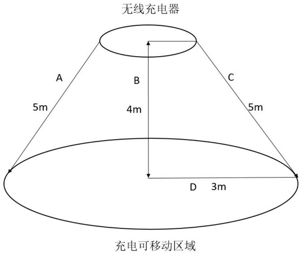
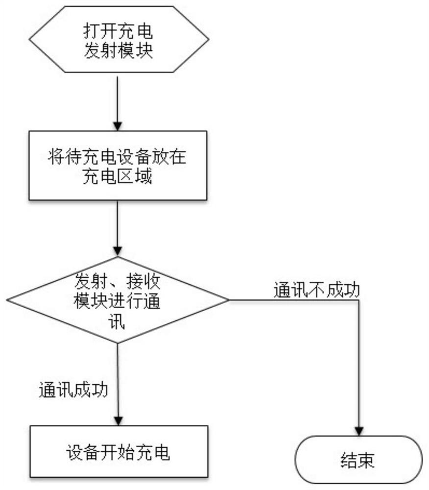
[0049] Such as image 3 As shown, according to a mobile wireless charging method provided by the present invention, the mobile wireless charging system of Embodiment 1 is adopted, and the transmission module is used within the working range of the transmission module (such as figure 1 Shown) one or more receiving modules for wireless charging.

[0050] Specifically, the first detection and identification module in the transmitting module first communicates with the second detection and identification module in the receiving module within the working range, and when it is recognized that the charging protocols of the transmitting module and the receiving module match, the first detection and identification The module turns on the series resonant circuit on the primary side, and the second detection and identification module turns on the series resonant circuit on the secondary side.

[0051] In this embodiment, there is one transmitting module, and one or more receiving module...

Embodiment 3

[0053] Considering that it is easy to encounter the situation that there is no transmitting module outdoors, such as Figure 4 As shown, in this embodiment, on the basis of Embodiment 1, a transmitting module and a receiving module are installed on the same device at the same time. In this way, when a device needs to be charged, the device to be charged can be wirelessly charged through the transmitting module on the other device.


PUM


Abstract

The invention provides a movable wireless charging system and method, and electronic equipment. The system comprises a transmitting module and a receiving module, the transmitting module comprises a primary side series resonance circuit, and the receiving module comprises a secondary side series resonance circuit. By adopting a magnetic resonance wireless charging mode, the constraint of a charging wire is eliminated, and a wireless charging problem of terminal products such as VR, AR and MR applied to a mobile scene is solved. By adopting a magnetic resonance wireless charging mode, long-distance, large-range and multi-device simultaneous charging can be realized.

Description

technical field [0001] The present invention relates to the field of wireless charging, in particular to a mobile wireless charging system, method and electronic equipment suitable for medium and long distances. Background technique [0002] Terminal products used in mobile scenarios such as VR, AR, and MR are currently subject to comprehensive considerations of battery technology and wearability. The power consumption speed is relatively fast, and they need to be charged after a certain period of use. Patent document CN105429247A discloses a charging device for VR glasses and a mobile terminal. The USB interface of the mobile terminal supplies power to the VR glasses through an external power supply device; or the USB interface of the mobile terminal is electrically connected to the charging interface of the VR glasses, so that the mobile terminal supplies power to the VR glasses. This charging method is just a conventional way to use other devices with power supply to powe...

Claims


Application Information

Patent Timeline
Patent Type & Authority Applications(China)
IPC IPC(8): H02J50/12H02J50/90H02J50/80H02J7/02
CPCH02J7/02H02J50/12H02J50/80H02J50/90
Inventor 黄正江孙立
Owner 上海影创信息科技有限公司
Why Eureka
Try Eureka