
Lifting driving device with one-way brake locking function

A lifting drive and locking technology, which is applied in the field of electric lifting tables, can solve problems such as sliding down and electric lifting tables that cannot be locked, and achieve the effect of avoiding sliding and increasing friction

Inactive Publication Date: 2021-02-23
NANTONG JIUZHENG ERGONOMICS CO LTD
View PDF7 Cites 1 Cited by
  • Summary
  • Abstract
  • Description
  • Claims
  • Application Information

AI Technical Summary

Problems solved by technology

[0004] The technical problem to be solved by the present invention is to provide a one-way brake locking function that can prevent the electric lifting table from sliding down when the load increases, aiming at the problem that the electric lifting table cannot be locked and slides under the condition of heavy load. Lifting drive

Method used


Image

  • Lifting driving device with one-way brake locking function
  • Lifting driving device with one-way brake locking function
  • Lifting driving device with one-way brake locking function

Examples


Embodiment Construction

[0025] The present invention will be further described below in conjunction with specific preferred embodiments, but the protection scope of the present invention is not limited thereby.

[0026] For the convenience of description, the relative positional relationship of each component, such as: the description of up, down, left, right, etc., is described according to the layout direction of the drawings in the specification, and does not limit the structure of this patent.

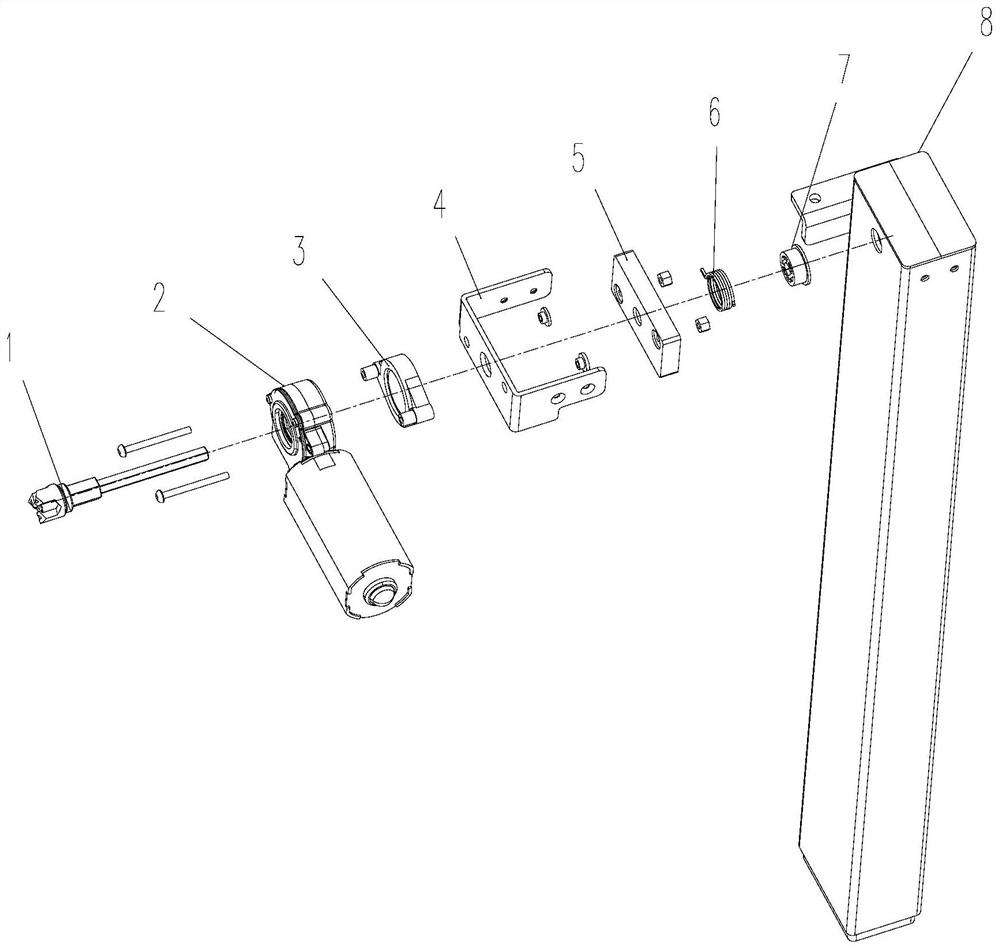
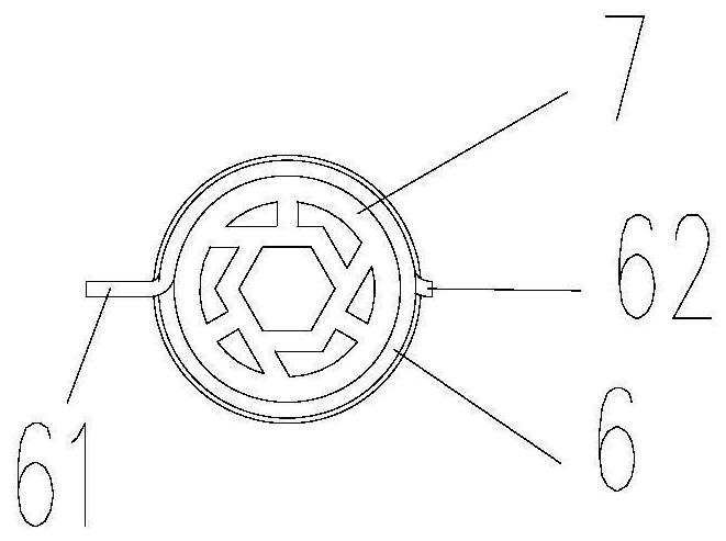
[0027] Such as figure 1 - Figure 8 As shown, an embodiment of the lifting drive device with one-way brake locking function of the present invention includes a transmission shaft 1, a motor 2, a fixed gasket 3, a support member 4, a brake seat shell 5, a brake spring 6, a brake seat 7, a lift Column assembly 8.

[0028] The output shaft of the motor 2 is fixedly connected to the transmission shaft 1, and the two ends of the transmission shaft 1 are respectively connected to the screw elevator in a lifti...


PUM


Abstract

The invention discloses a lifting driving device with a one-way brake locking function, which is characterized in that a transmission shaft (1) of the lifting driving device is connected with a spirallifter in a lifting upright post assembly (8), and a locking structure is arranged on the transmission shaft; the locking structure comprises a brake base shell (5) installed on the transmission shaft in a clearance fit mode, a brake base (7) installed on the transmission shaft in an interference fit mode and a brake spring (6) installed on the brake base in an interference fit mode, an installation groove (51) is formed in the brake base shell, the brake base is installed in the installation groove, and the brake spring is a spiral spring. The rotation direction of the spiral spring is consistent with the rotation direction of the transmission shaft and the brake base when the lifting stand column assembly extends, the spiral spring is provided with a first end (61) and a second end (62), the first end is limited by the installation groove, and the second end is in a free state. Locking of the lifting driving device during contraction can be realized, so that the lifting driving device does not slide down during load bearing.

Description

technical field [0001] The invention relates to an electric lifting table, in particular to a lifting driving device with a one-way braking and locking function. Background technique [0002] The electric lift table can change the height of the table body to meet people's individual needs, so that people can work and study in the most comfortable posture. [0003] As shown in Chinese patent CN209732949U, electric lift tables on the market generally use a motor-driven screw jack to realize the lifting function. In order to increase the lifting speed of the electric lifting table, the industry usually shortens the screw lead of the screw lift to achieve this, which leads to the inability of the electric lifting table to stop under a certain load, that is, the lifting structure of the electric lifting table after bearing the load. In the process of driving the heavy-duty desktop down, the desktop cannot be locked, and the desktop slides down. Contents of the invention [00...

Claims


Application Information

Patent Timeline
Patent Type & Authority Applications(China)
IPC IPC(8): H02K7/102H02K7/06A47B9/00A47B13/02
CPCH02K7/102H02K7/06A47B9/00A47B13/02A47B2200/0056
Inventor 赵振普
Owner NANTONG JIUZHENG ERGONOMICS CO LTD
Learn More