
Electric main shaft and machine tool

An electric spindle and shaft core technology, which is used in grinding machine parts, maintenance and safety accessories, metal processing machinery parts, etc., can solve the problems of elongation fluctuation, inconsistency in elongation, and difference in machining accuracy at both ends of the spindle. , to achieve the effect of eliminating elongation, maintaining stable processing accuracy and stable processing performance

Pending Publication Date: 2022-02-25
GUANGZHOU HAOZHI ELECTROMECHANICAL
View PDF6 Cites 0 Cited by
  • Summary
  • Abstract
  • Description
  • Claims
  • Application Information

AI Technical Summary

Problems solved by technology

With this design structure, when the spindle rotates at high speed, the elongation at both ends of the shaft core after heating is inconsistent, and most of the elongation will be concentrated on the floating side of the outer ring of the bearing, so the machining accuracy at both ends of the spindle will be reduced. difference
At the same time, the shaft core is designed as an integrated structure, and the elongation generated by the heat inside the shaft core cannot be eliminated, which will cause fluctuations in the elongation at both ends of the shaft core, which will eventually affect the machining accuracy of the spindle.

Method used


Image

  • Electric main shaft and machine tool
  • Electric main shaft and machine tool
  • Electric main shaft and machine tool

Examples


Embodiment Construction

[0026] This part will describe the specific embodiment of the present invention in detail, and the preferred embodiment of the present invention is shown in the accompanying drawings. Each technical feature and overall technical solution of the invention, but it should not be understood as a limitation on the protection scope of the present invention.

[0027] In the present invention, "several" means one or more, "multiple" means more than two, "greater than", "less than", "exceeding", etc. are understood as excluding the original number; "above", "below", "within" " and so on are understood as including the original number. In the description of the present invention, if "first" and "second" are used only for the purpose of distinguishing technical features, it should not be understood as indicating or implying relative importance or implicitly indicating the number of indicated technical features or Implicitly indicates the sequence of the indicated technical features.

...


PUM


Abstract

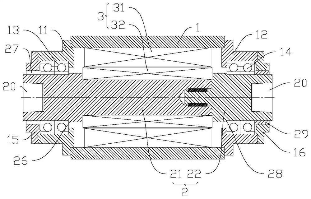
The invention discloses an electric main shaft and a machine tool. The electric main shaft comprises a machine body, a shaft core assembly and a motor; the shaft core assembly comprises a first shaft core and a second shaft core; the first shaft core and the second shaft core are coaxially connected to form the shaft core assembly capable of synchronously rotating together; the first shaft core and the second shaft core can float in the axial direction at the joint so as to absorb the elongation generated when the shaft core assembly is heated; the shaft core assembly penetrates through an inner cavity of the machine body; the first shaft core is supported on a first bearing seat through a first bearing, the outer ring of the first bearing is locked on the first bearing seat in the axial direction, and the inner ring of the first bearing is locked on the first shaft core in the axial direction; the second shaft core is supported on a second bearing seat through a second bearing, the outer ring of the second bearing is locked on the second bearing seat in the axial direction, and the inner ring of the second bearing is locked on the second shaft core in the axial direction; and the motor comprises a stator and a rotor. The elongation in the shaft cores is eliminated, so that the elongation at the two ends of each shaft core is kept stable, and finally, the machining performance of the two ends of the main shaft is consistent and stable.

Description

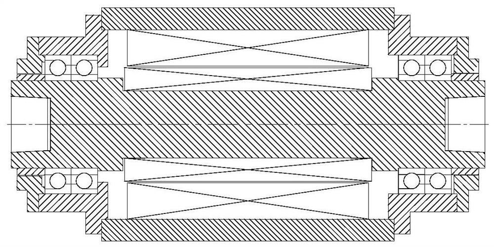
technical field [0001] The invention is used in the field of mechanical processing, and in particular relates to an electric spindle and a machine tool. Background technique [0002] As the core component of the machine tool, the performance of the spindle directly affects the machining accuracy of the product. When the processing accuracy of the main shaft cannot meet the requirements, the processed products cannot reach higher accuracy. Therefore, only by continuously improving the machining performance of the spindle can the machining accuracy of the machine tool be continuously improved. [0003] When the spindle rotates at high speed, the shaft core is heated and the axial length changes, which affects the processing performance of the product. Therefore, how to control the change of the shaft core elongation is very important. In the existing technology, such as figure 1 As shown, the shaft core of the main shaft is a one-piece shaft core, the inner and outer rings...

Claims


Application Information

Patent Timeline
IPC IPC(8): B23B19/02B23Q11/12B24B41/04B24B41/00
CPCB23Q1/70B23Q11/127B24B41/04B24B41/00
Inventor 蒋勇雷群汤丽君汤秀清
Owner GUANGZHOU HAOZHI ELECTROMECHANICAL
Learn More